
Ever since I wrote about timer interrupts, a number of readers have asked me on how to generate a 16-bit pulse width modulation (PWM) signal with Arduino. Well, here it is.
Arduino PWM Background
PWM has a lot of uses in the microcontroller world. The most common are dimming a LED or controlling the speed of a DC motor.
Most of us are familiar with Arduino’s analogWrite() function in generating PWM:
analogWrite(pin, value)
The function accepts two parameters: pin and value and returns nothing. Both parameters are of int type, a 16-bit data type. However, the documentation specifies that the value parameter must be between 0 and 255, which makes it essentially an 8-bit variable.
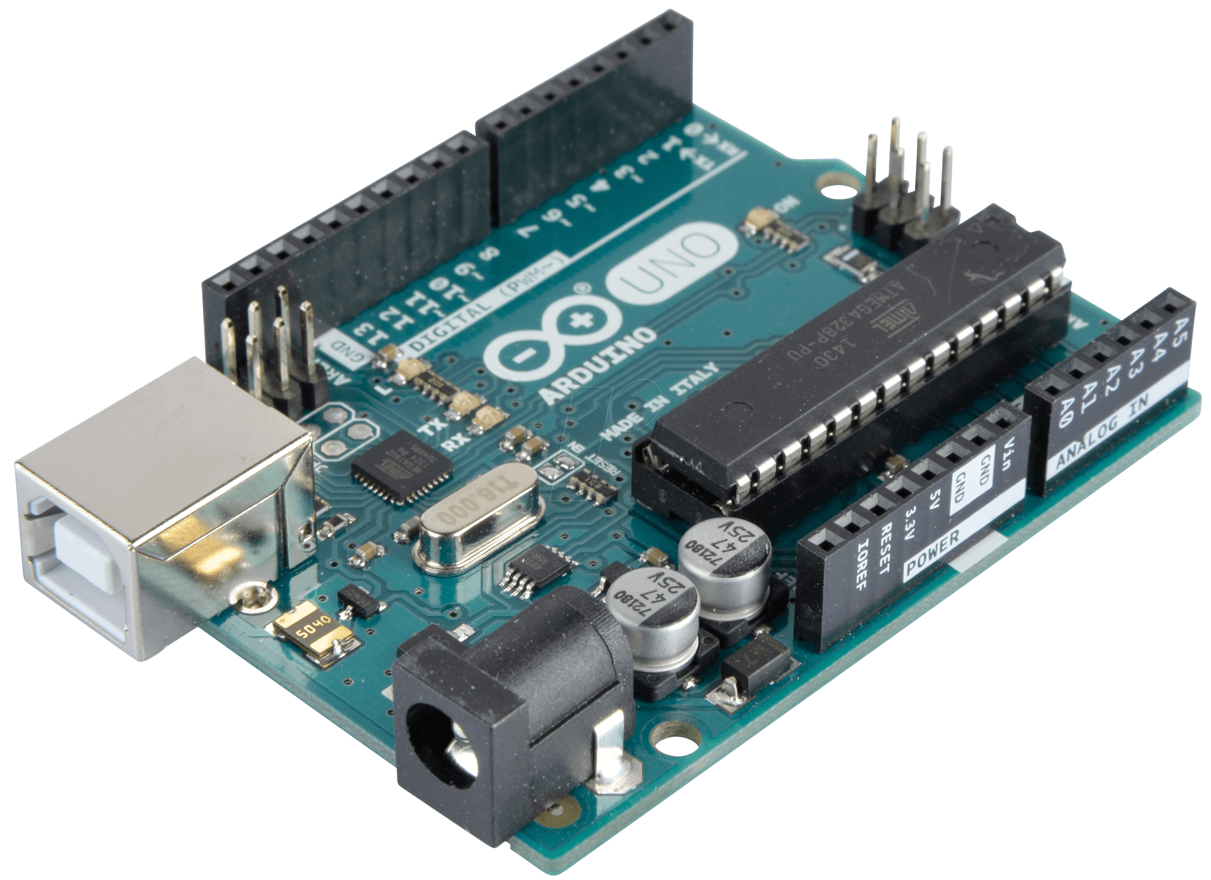
The Arduino UNO contains three timers: two 8-bit (Timer0 and Timer2) and one 16-bit (Timer1). In fact, the timer used depends on the PWM pin you specify:
- Timer0 = Pins 5, 6
- Timer1 = Pins 9, 10
- Timer2 = Pins 11, 3
So this uses Timer0:
analogWrite(5, 100);
While this uses Timer2:
analogWrite(11, 100);
This one uses Timer1 but is this possible?
analogWrite(9, 30000);
Here, we set the value parameter to 30000 which is obviously beyond 255 but within the limits of the int variable. Will this do anything?
Dissecting the AnalogWrite Function
To answer the question above, we will look at how analogWrite() is implemented. The function definition resides on wiring_analog.c on the Arduino core.
Here’s some part of the function:
void analogWrite(uint8_t pin, int val)
{
   ...
   pinMode(pin, OUTPUT);
   if (val == 0)
   {
      digitalWrite(pin, LOW);
   }
   else if (val == 255)
   {
      digitalWrite(pin, HIGH);
   }
   else
   {
      switch(digitalPinToTimer(pin))
      {
         ...
         #if defined(TCCR0A) && defined(COM0A1)
         case TIMER0A:
         // connect pwm to pin on timer 0, channel A
            sbi(TCCR0A, COM0A1);
            OCR0A = val; // set pwm duty
            break;
         #endif

         #if defined(TCCR0A) && defined(COM0B1)
         case TIMER0B:
         // connect pwm to pin on timer 0, channel B
            sbi(TCCR0A, COM0B1);
            OCR0B = val; // set pwm duty
            break;
         #endif

         #if defined(TCCR1A) && defined(COM1A1)
         case TIMER1A:
         // connect pwm to pin on timer 1, channel A
            sbi(TCCR1A, COM1A1);
            OCR1A = val; // set pwm duty
            break;
         #endif

         #if defined(TCCR1A) && defined(COM1B1)
         case TIMER1B:
         // connect pwm to pin on timer 1, channel B
            sbi(TCCR1A, COM1B1);
            OCR1B = val; // set pwm duty
            break;
         #endif

        ...
The rest of the code is just the same bits repeating for the other timers on other Arduino boards.
Interestingly, the function takes values zero and 255 as extremes:
if (val == 0)
{
   digitalWrite(pin, LOW);
}
else if (val == 255)
{
   digitalWrite(pin, HIGH);
}
This means writing 0 to value just clears the pin while writing 255 sets the pin. Note that you can still write beyond 255 since after this, an else statement is found:
switch(digitalPinToTimer(pin))
{
   …
   #if defined(TCCR0A) && defined(COM0A1)
   case TIMER0A:
   // connect pwm to pin on timer 0, channel A
      sbi(TCCR0A, COM0A1);
      OCR0A = val; // set pwm duty
      break;
   #endif

   #if defined(TCCR0A) && defined(COM0B1)
   case TIMER0B:
   // connect pwm to pin on timer 0, channel B
      sbi(TCCR0A, COM0B1);
      OCR0B = val; // set pwm duty
      break;
   #endif

   #if defined(TCCR1A) && defined(COM1A1)
   case TIMER1A:
   // connect pwm to pin on timer 1, channel A
      sbi(TCCR1A, COM1A1);
      OCR1A = val; // set pwm duty
      break;
   #endif

   #if defined(TCCR1A) && defined(COM1B1)
   case TIMER1B:
   // connect pwm to pin on timer 1, channel B
      sbi(TCCR1A, COM1B1);
      OCR1B = val; // set pwm duty
      break;
   #endif

...
The digitalPinToTimer() function determines which timer is for the given pin.
So there’s nothing wrong when we do this:
analogWrite(9, 30000)
The value 30000 passes to the corresponding OCRxx register.
However the OCRxx registers for both Timer0 and Timer2 are 8-bit registers so passing a value beyond 255 will mess up PWM generation (e.g. only the low byte will be read for values beyond 255). Of course, this is not the case for the 16-bit Timer1.
How AnalogWrite() Works for Timer1
I recommend you read Secrets of Arduino PWM for an explanation on how PWM is generated for the 8-bit timers. Here, I will focus on the 16-bit Timer1 timer.
Going back on the snippet above, we see this part:
#if defined(TCCR1A) && defined(COM1A1)
case TIMER1A:
// connect pwm to pin on timer 1, channel A
   sbi(TCCR1A, COM1A1);
   OCR1A = val; // set pwm duty
   break;
#endif
The #if #endif here makes the code safe for Arduino boards that might not have a Timer1 timer. Then we see that COM1A1 is set:
sbi(TCCR1A, COM1A1);
We wouldn't know what this mean unless we know what mode Timer1 is on.
Configuring Timer1
There are two channels (and pin) that we can use with Timer1. Channel A is OC1A or digital pin 9 and Channel B is OC1B is or digital pin 10. For simplicity, let’s focus on Channel A (output on D9).
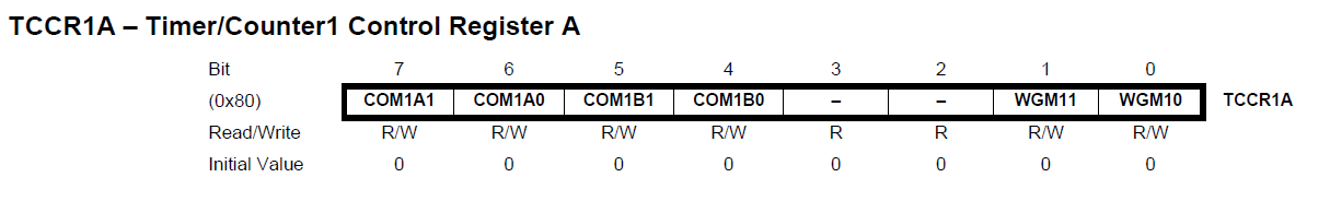
Settings for Channel A requires manipulating a pair of bits, COM1A1 and COM1A0. The combination to use depends on what mode the Timer1 is in.
There are five distinct modes:
- Normal
- Clear Timer on Compare
- Fast PWM
- Phase Correct PWM
- Phase and Frequency Correct PWM.
Bits WGM13, WMG12, WGM11 and WGM10 configure the mode. These bits are in the TCCR1A (bits 1 and 0) and TCCR1B (bits 4 and 3) registers respectively. Moreover, COM1A1 and COM1A0 is also on TCCR1A.
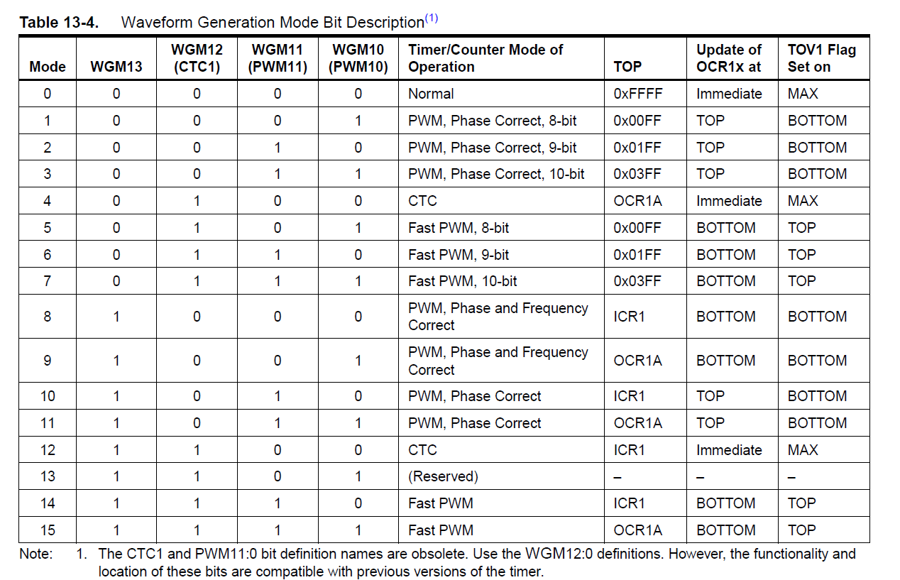
The combination of WGM13:10 bits and what mode they represent is on table 13-4:
Looking at wiring.c, we see this:
#if defined(TCCR1A) && defined(WGM10)
   sbi(TCCR1A, WGM10);
#endif
This means only WGM10 is set and the rest is clear. This corresponds to mode 1 on Table 13-4 above. Interestingly, this is an 8-bit PWM mode. More on this later.
Since we know what mode we are in, we know which table to look at.
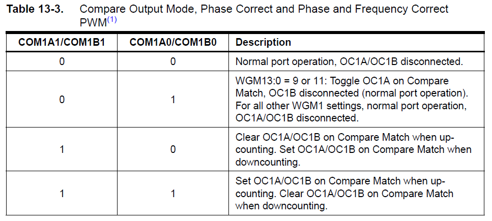
Recall that COM1A1 is set while COM1A0 is clear. Thus, our chosen configuration is a compare match, with OC1A (D9) clear when matched on up-counting and set when matched on down-counting.
What is Phase Correct PWM?
Looking back to Table 3-4, we see that the Arduino core chooses mode 1, with the description PWM, Phase-correct, 8 bits. Here's how the ATMega328p defines phase correct PWM:
The phase correct Pulse Width Modulation or phase correct PWM mode (WGM13:0 = 1, 2, 3, 10, or 11) provides a high resolution phase correct PWM waveform generation option. The phase correct PWM mode is, like the phase and frequency correct PWM mode, based on a dualslope operation. The counter counts repeatedly from BOTTOM (0x0000) to TOP and then from TOP to BOTTOM. In non-inverting Compare Output mode, the Output Compare (OC1x) is cleared on the compare match between TCNT1 and OCR1x while upcounting, and set on the compare match while downcounting. In inverting Output Compare mode, the operation is inverted. The dual-slope operation has lower maximum operation frequency than single slope operation. However, due to the symmetric feature of the dual-slope PWM modes, these modes are preferred for motor control applications.
Basically, the register which counts from 0 to 65535 (2^16) is register TCNT1. You can say that TCNT1 is really Timer1 but they just chose a different name.
In phase correct PWM mode, this counter counts from 0x0000 to a value the datasheet calls TOP then back to 0x0000 again. If you go back to table 13-4, TOP in the chosen mode is only 0x00FF or 255, hence the "8-bit" on the mode name.
So this counter counts, independently from the program, at a rate of:
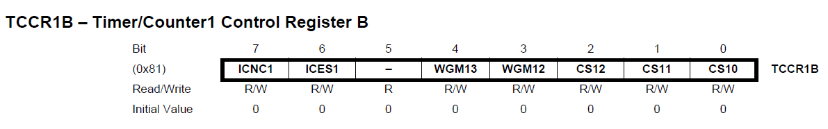
We can decrease this rate by using a prescaler configurable through TCCR1B:
Bits CS10, CS11 and CS12 dictate the prescale value. Table 13-5 shows what each bit combination means:
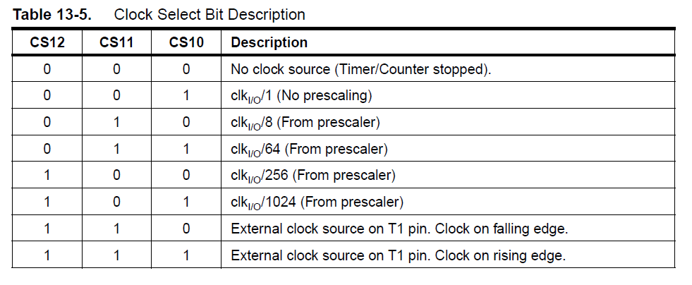
The default prescale setting in Arduino is in wiring.c:
#if defined(TCCR1B) && defined(CS11) && defined(CS10)
   TCCR1B = 0;
   // set timer 1 prescale factor to 64
   sbi(TCCR1B, CS11);
   #if F_CPU >= 8000000L
   sbi(TCCR1B, CS10);
#endif
Here we see the CS11 and CS10 are set while CS12 is clear. This corresponds to a prescale of 64 from Table 13-5. This means the actual rate for Timer1 is
That’s 1.028 millisecond per count.
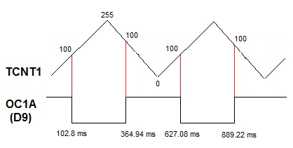
PWM signal now comes out of D9 because OC1A (ATMega name for D9) clears when the counter (TCNT1) matches with OCR1A while going up and sets OC1A when the counter is going down.
OCR1A’s value is what we are setting when we call analogWrite(). For example:
analogWrite(9, 100);
This gives OCR1A a value of 100. When TCNT1 (while upcounting) equals this value, the OC1A (D9) pin goes low. Conversely, when TCNT1, while downcounting equals this value, the OC1A pin goes high.
The waveform probably looks like this:
What if we go beyond 255 like this?
analogWrite(9, 512);
Since Timer1 or TCNT1 reaches its peak at 255, setting OCR1A to 512 does nothing.
A True 16-bit PWM
We can generate a 16-bit PWM if we completely forget about analogWrite() and write our own function.
First we need to choose the correct mode. We have plenty of options if we want a 16-bit PWM. Let's go back to Table 13-4:
For this article, I’ll be using mode 8. Here, the TOP value to which TCNT1 can count is defined by a register named ICR1. This is better because of a couple of reasons:
- OCR1A is a double buffer register which makes it easier to update dynamically
- It produces a more symmetrical pulse (see section 13.9.5 of ATMega328p datasheet)
First step is to define the mode through register TCCR1A and TCCR1B
TCCR1A = (TCCR1A & B00111100) | B10000010;   //Phase and frequency correct, Non-inverting mode, TOP defined by ICR1
TCCR1B = (TCCR1B & B11100000) | B00010001;   //No prescale
Here, bit COM1A1 (TCCR1A bit 7) is set while COM1A0 (TCCR1A bit 6) is cleared (see Table 13-3 above). We also cleared bits WGM10 (TCCR1A bit 0), WGM11 (TCCR1A bit 1) and WGM12 (TCCR1B bit 3) while setting WGM11 (TCCR1B bit 4). We also will not be using any prescale (bits 2:0 of TCCR1B = 001).
Next, we define the TOP value of TCNT1 (Timer1):
ICR1 = 0xFFFF;
This means the counter will now count from 0 to 65535.
To update our waveform, we only need to write on the OCR1A register. For example, this will clear the D9 pin every time TCNT1 reaches 100:
OCR1A = 100;
This will result in a PWM signal like this:
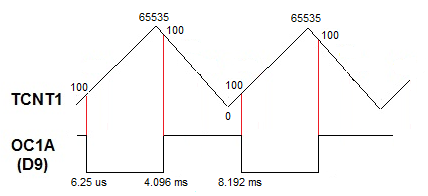
This is a PWM signal with a pulse width of 4.096 ms.
Here’s now our full sketch:
void setup() {
  Serial.begin(9600);
  pinMode(9, OUTPUT);
  TCCR1A = (TCCR1A & B00111100) | B10000010;   //Phase and frequency correct, Non-inverting mode, TOP defined by ICR1
  TCCR1B = (TCCR1B & B11100000) | B00010001;   //No prescale
  ICR1 = 0xFFFF;
}

void loop() {
  //Increasing pulse
  for(unsigned int i=0;i<65535;i++){
     pwm_16(i);
  }
 //Decreasing pulse
  for(unsigned int j=65535;j!=0;j--){
    pwm_16(j);
  }
}

void pwm_16(int val){
  OCR1A = val;
}
If an LED is attached to pin 9, this sketch will fade up the LED in 65535 counts and then fade down the LED in the same count.
That's it for this Arduino 16-bit PWM tutorial. For questions or reactions for this article, kindly drop a comment below.

