
I2C, or Inter-integrated Circuit, is a communications protocol common in microcontroller-based systems, particularly for interfacing with sensors, memory devices and liquid crystal displays. Similar to SPI, it's a synchronous protocol because it uses a clock line. The I2C protocol, however, uses less pins and is a much more robust standard.
I2C Basics
Asynchronous serial protocols like RS-232 (UART) is for one-is-to-one communication only. Moreover, the additional two-bits (start and stop) used in UART transmission adds overhead and thus wastes a part of the data rate.
Both SPI and I2C are capable of one-is-to-many transmission. However, SPI needs at least four pins (MOSI, MISO, SCK, SS) and doesn’t support multiple masters. And while SPI is the fastest out of the three, speed isn’t everything.
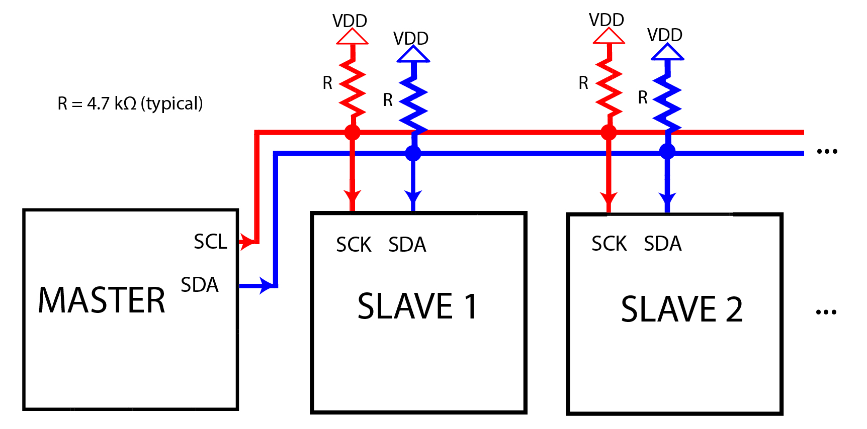
The I2C protocol requires only an SDA and SCL pin. SDA is short for Serial Data Line and SCL is short for Serial Clock Line. These two bidirectional lines have pull-up resistors.
[the_ad id="3059"]
The pull-up resistor value depend on a number of factors. Texas Instruments recommends the following formulas to calculate the correct pull-up resistor value:
![]()
![]()
Where VOL is the logic low voltage, IOL the logic low current, tr is the maximum rise time of the signal and Cb is the bus (wire) capacitance.
If you don’t want to bother calculating the resistor value, use the typical 4.7 kΩ.
Having pull-up resistors is an open-drain scheme. Bus devices pull-down the voltage on the bus instead of using their own operating voltage. This allows devices with different operating voltages to be usable but only if the lower voltage is still readable by the higher-voltage device. For example, it’s OK to connect a 3.3V I2C sensor to a 5V arduino because the latter can still read 3.3V. But a 5V I2C sensor will not work with a 3.3V microcontroller.
I2C Timing
SPI is simple enough that you can implement it through bit-banging or use shift registers to read its data. I2C, however, is a more complex protocol. The image below (click to enlarge) best describes the protocol:
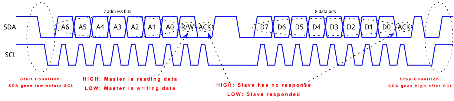
Both SDA and SCL lines are high when idle. A start condition occurs when the SDA goes low before the SCL. Data goes out immediately following the start condition. The stop condition signals the end of transmission. A stop condition occurs when the SDA goes high after SCL.
I2C Address
There is no slave select (SS) line, so I2C devices each have their own addresses to identify them. During transmission by the master device, the I2C address goes out first. I2C devices typically have multiple registers with their own addresses. Thus, after the I2C address, the register address may follow. Finally, the data from (or to) the device is readable from the bus.
[the_ad id="3059"]
The I2C address consists of 7 bits, plus the R/W bit and the ACK bit. The R/W bit specifies if the master is sending data or requesting data. The ACK bit tells the master if the slave responded or not. When the master is initially sending data, the ACK bit is low.
If there are 7 bits for address, then there should be 27 or 128 possible addresses. Out of the 128 possible, there are 8 reserved addresses:
| 8-bit byte | Description | ||
| 7-bit address | R/W value | ||
|
MSB (4-bit) |
LSB (3-bit) |
1-bit | |
| 0000 | 000 | 0 | General call |
| 0000 | 000 | 1 | Start byte |
| 0000 | 001 | X | CBUS address |
| 0000 | 010 | X | Reserved for different bus format |
| 0000 | 011 | X | Reserved for future purpose |
| 0000 | 1XX | X | HS-mode master code |
| 1111 | 1XX | 1 | Device ID |
| 1111 | 0XX | X | 10-bit slave addressing |
An easier way to look at this table is that reserved addresses are 0000 XXXX to 1111 XXXX. The last (rightmost) bit is the R/W bit so it's not included for addresses. Therefore, if you exclude the addresses in the table above, the usable I2C addresses are from 0010000 (0x10) to 1110111 (0x77).
Some devices include the R/W bit when stating the address. For example, the device datasheet may say the address is 0x88 which is not included in the usable I2C addresses. In reality, the R/W was included and the address is really 0x42.
Implementing I2C
Arduino
The Wire library is built to use the I2C hardware on the Arduino UNO. Just like SPI, the I2C pins are specific and is found on A4 and A5.

The Arduino UNO board has two I2C ports. However, the extra port near the reset button is connected to the same pins on A4 and A5. Moreover, two ports doesn't really mean anything here because you can connect multiple devices on a bus.
[the_ad id="3059"]
To use the Wire library, the Wire.h header must be included on top of the code.
The use of the library starts when this is written:
Wire.begin();
If the parameter is empty, this means the Arduino is the master device. If the Arduino is a slave, the parameter is the bus address of the Arduino.
To communicate to a slave, this function follows:
Wire.beginTransmission(slave_address);
Writing data to the device uses the write() function:
Wire.write();
If reading data from the device, we use the read() function.
Wire.read();
Ending the I2C transmission requires this function:
Wire.endTransmission();
See I2C example below for a specific use of the Wire library.
PIC
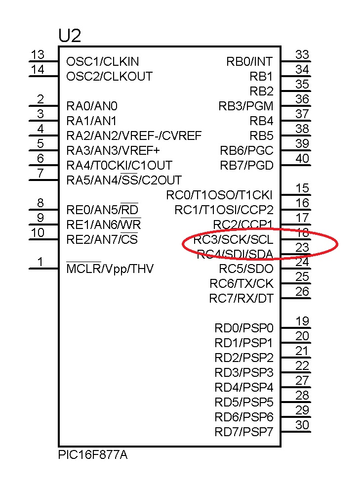
I2C communication for PIC uses the MSSP module. This module is in charge of both SPI and I2C so there’s no way to use both simultaneously, at least, for PIC16 devices. Similar to the Arduino UNO, the PIC has its own SDA and SCL pins.
Here’s a more detailed tutorial for PIC I2C.
I2C Example
To help you visualize the protocol, let’s use the MPU6050 as an example device.
The MPU6050 is an accelerometer and gyroscope integrated circuit that communicates via the protocol. This device has an address of 110100X where X is the state of one of its pin, AD0. The use of AD0 as the last bit allows the use of two MPU6050 in the same bus. The first device could use the address 0x68 while another uses 0x69. This is important as you cannot use two devices one the same bus with the same addresses!
The MPU6050 gives acceleration and gyroscope in X, Y, Z as 16-bit values. This means each value is in two registers: high byte and low byte.
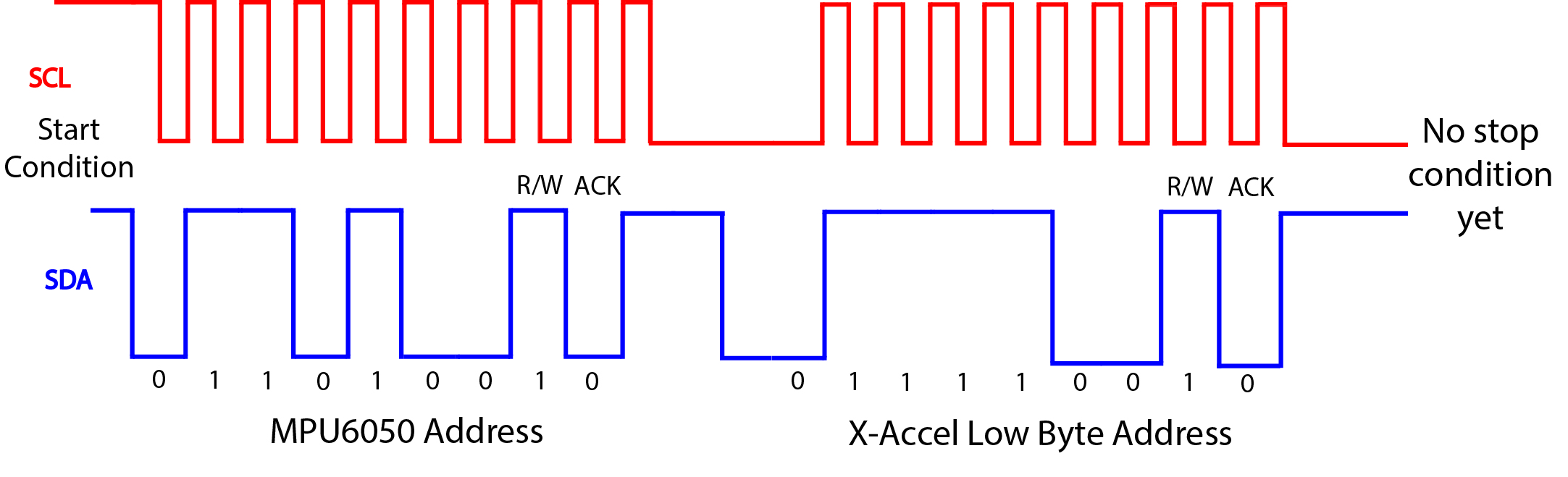
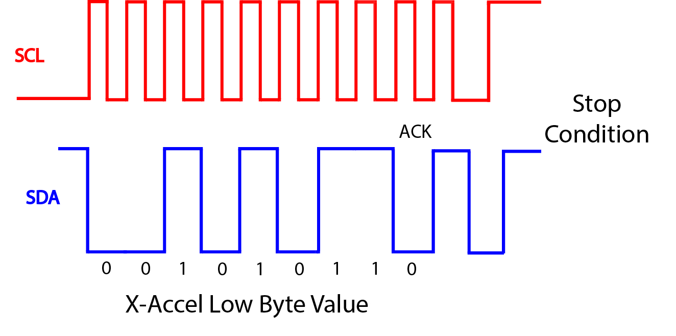
For simplicity, let’s say you want your Arduino to read only the low-byte of X acceleration. Also, let’s assume that the MPU6050 is already a wake (FYI, you need to wake it up by writing 0x00 to Power Management Register 0x6B). This would be the sequence:
- I2C Start condition
- Write the device address (0x68, assuming AD0 is low)
- Write the register address of the low byte of X-acceleration (0x3C)
- The device will send out the low byte of the X-acceleration
- I2C Stop condition
The timing diagram for the steps above would be like this:
Here’s the Arduino sketch of the sequence above:
#include<Wire.h>

const int MPU_addr=0x68; // I2C address of the MPU-6050
char AcX_LOW

void setup(){
    Wire.begin();
}
void loop(){
    Wire.beginTransmission(MPU_addr);
    Wire.write(0x3C); // starting with register 0x3B (ACCEL_XOUT_H)
    Wire.endTransmission(true);
    AcX_LOW=Wire.read();
}
There are other peculiarities with this protocol, including clock stretching and repeated start. I will cover that in the next part of this tutorial.

