
SPI, short for Serial Peripheral Interface, is a communication protocol common in microcontroller systems. Sensors, liquid crystal displays and memory cards are examples of devices that use SPI. It is faster than both UART and I2C although it also has its disadvantages.
SPI Protocol Basics
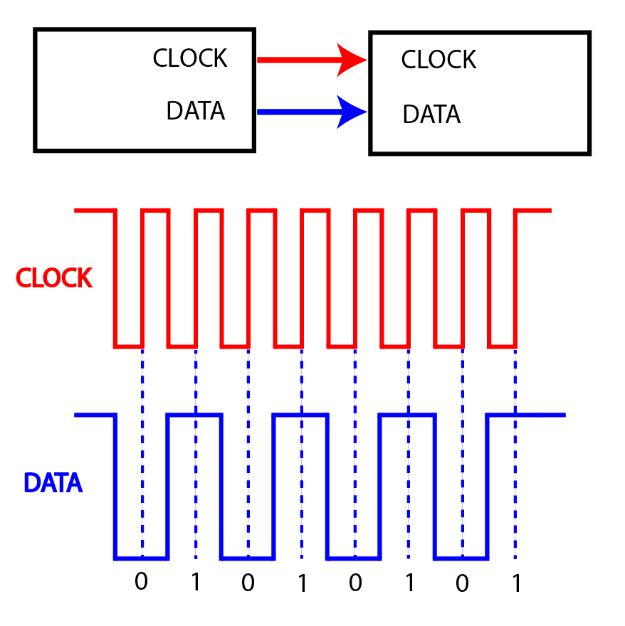
SPI, same with I2C, is a synchronous protocol because there is a separate clock line. In contrast, RS232 (UART) is an asynchronous protocol because there is no clock line. The clock pulse in SPI is for synchronizing the transmitter and the receiver.
 [the_ad id="3059"]
Recall that for UART transmitters and receivers to synchronize, the baud rate between the two devices must agree and there must always be start and stop bits. There is no need for start and stop bits for SPI because the clock pulse dictates the flow of data.
Moreover, you don’t need to define the SPI speed of transmission. But there are instances where the transmitter might be too fast for the receiver so the option to define data rate is still there.
SPI Pins
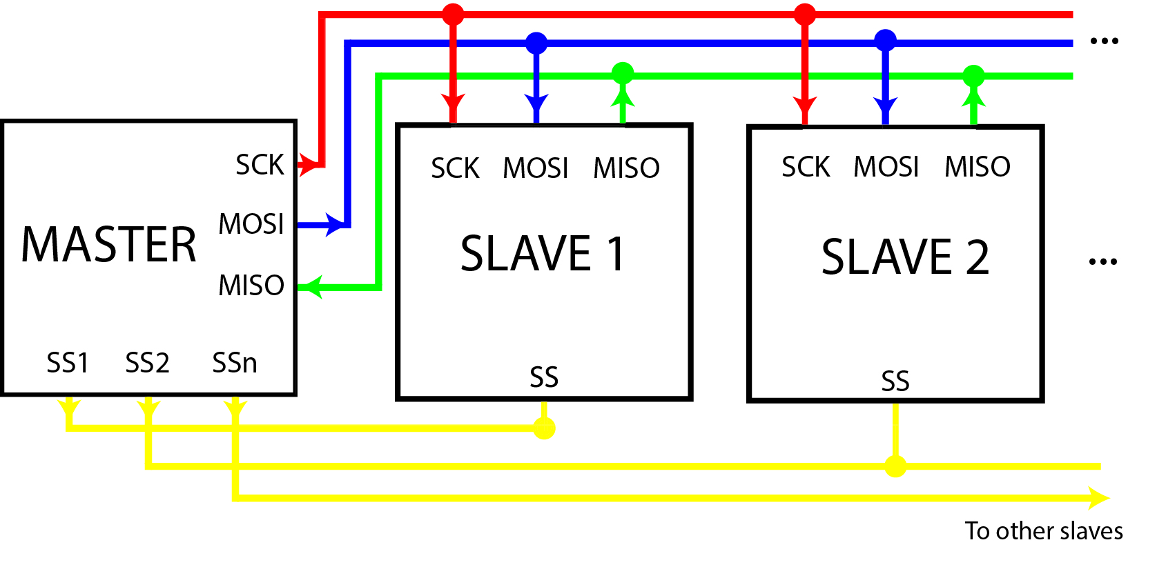
SPI uses three pins for communication: MOSI, MISO and SCLK. MOSI is short for Master-Out-Slave-In and MISO stands for Master-In-Slave-Out. This shows that SPI uses master-slave scheme and operates at full-duplex (simultaneous two-way communication).
[the_ad id="3059"]
The master device dictates the SPI parameters including the data rate, bit order and mode. The data rate is the SPI speed of transmission and depends on the microcontroller's clock speed. Bit order describes if the rightmost (LSB) or leftmost (MSB) is the first bit out. A more thorough discussion of mode is on the next section.
Only one master device is possible and the number of slaves, in general, depends on the number of Slave Select (SS) pins on the master device.
When a master wants to communicate with a slave, the SS line to that slave goes low while the rest go high. The data is then read on the MOSI line and the slave replies through the MISO line. There is no way for slaves to talk to the other slaves directly!
A good design practice is to add pull-up resistors on SS pins to effectively isolate slave devices from each other.
SPI is a de facto standard and a loose one at that. Thus, device manufacturers may have different ways to implement the protocol. It's best to read the device datasheet beforehand.
SPI Modes
The manner on when to send data with respect to the clock pulse is important. There are four ways to do this and thus there are four “SPI modes”.
|
Mode |
Clock Polarity | Clock Phase | Clock is Idle at... | Data is Shifted Out During... |
|
Mode 0 |
0 |
0 | Low | Falling Edge |
|
Mode 1 |
0 |
1 |
Low |
Rising Edge |
| Mode 2 |
1 |
0 |
High |
Rising Edge |
| Mode 3 | 1 | 1 | High |
Falling Edge |
Clock polarity is the state of the clock when its idle (no data) while clock phase tells which part of the pulse (rising edge or falling edge) should a data bit come out.
An example timing diagram for Mode 0:
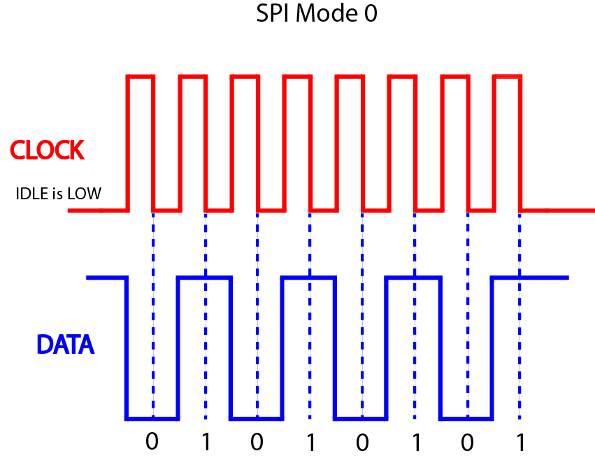
In this mode, one data bit comes out every falling edge of the pulse. The SCK line is low when idle. Another way of describing this mode is the SCK line goes high after each bit. For comparison, here’s a timing diagram for Mode 3:
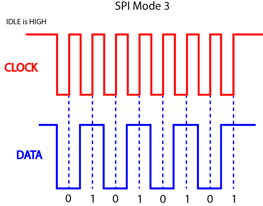
Here, the clock polarity is reversed (idle now is high) so the data bit is sent on the rising edge of the pulse or the SCK pin is pulsed low after each bit is sent.
[the_ad id="3059"]
While most devices use mode 0, it’s still important to know which SPI mode the device is using before interfacing it with a microcontroller. The mode is usually found in the device’s datasheet.
Implementing SPI
Arduino
The simple nature of SPI is one of its advantages. You can, in fact, implement SPI via software only. This function for an Arduino sketch delivers SPI signals in mode 0, LSB first:
void SPI_softwrite(char data) {
  for (int i = 0; i < 8; i++, data >>= 1) {
    digitalWrite(MOSI_pin, data & 0x01);
    digitalWrite(SCK_pin, HIGH); //after each bit sent, CLK is pulsed high
    delay(1);
    digitalWrite(SCK_pin, LOW);
    delay(1);
  }
}
Here, each bit of the variable data is sent out via the MOSI_pin. After it's sent, the SCK_pin is pulsed from high to low. The pulse width in this case is 1 millisecond.
If you’re asking how to implement mode 3 using the same function above, here’s how:
void SPI_softwrite(char data) {
  for (int i = 0; i < 8; i++, data >>= 1) {
    digitalWrite(MOSI_pin, data & 0x01);
    digitalWrite(SCK_pin, LOW); //after each bit sent, CLK is pulsed low
    delay(1);
    digitalWrite(SCK_pin, HIGH);
    delay(1);
  }
}
This is just the inverse of the previous sketch, i.e., the SCK_pin goes low then high after each bit.
I wouldn’t recommend using this function though. The Arduino IDE already has shiftIn() and shiftOut() functions that sends out SPI data from any pin.
For example, if you want to send the data 0x4F out from pin 8, this is how it's done using shiftOut():
shiftOut(8, 9, LSB, 0x4F)
This assumes you used pin 9 as the clock pin.
The disadvantage of using shiftIn() and shiftOut() or other software implemented SPI is lower speed. The shiftout() function relies on digitalWrite() which means its top speed is 142 kHz on the UNO.
The SPI library utilizes the built-in SPI hardware inside microcontrollers. The disadvantage of this approach, however, is the MOSI, MISO and SCK pins are specific.
Arduino SPI Pins
For the Arduino UNO, the MOSI, MISO, SCK and SS pins are found at pins 11, 12, 13 and 10 respectively:
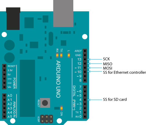
To use the Arduino’s SPI library, the SPI.h header must be part of the sketch. SPI.begin() then starts the library and a call on SPI.transfer() transfers data. By default, the SPI transaction is in mode 0. The SPI.beginTransaction() allows the use of other modes. For example:
SPI.beginTransaction(SPISettings(14000000, MSBFIRST, SPI_MODE1))
Where the first parameter is the data rate, then the bit order and the mode.
[the_ad id="3059"]
You can use the SPI library without using transactions. However, I recommend using transactions especially when there are multiple slaves. Transactions allow proper sharing of the SPI bus.
Moreover, you can use interrupts for better slave device management:
SPI.begin();
SPI.usingInterrupt(digitalPinToInterrupt(int_pin));
attachInterrupt(digitalPinToInterrupt(int_pin), whatever_function, LOW);
Here, the code jumps to whatever_function when the slave device issues an interrupt.
Check out this example on how to use a specific device using SPI on an Arduino UNO.
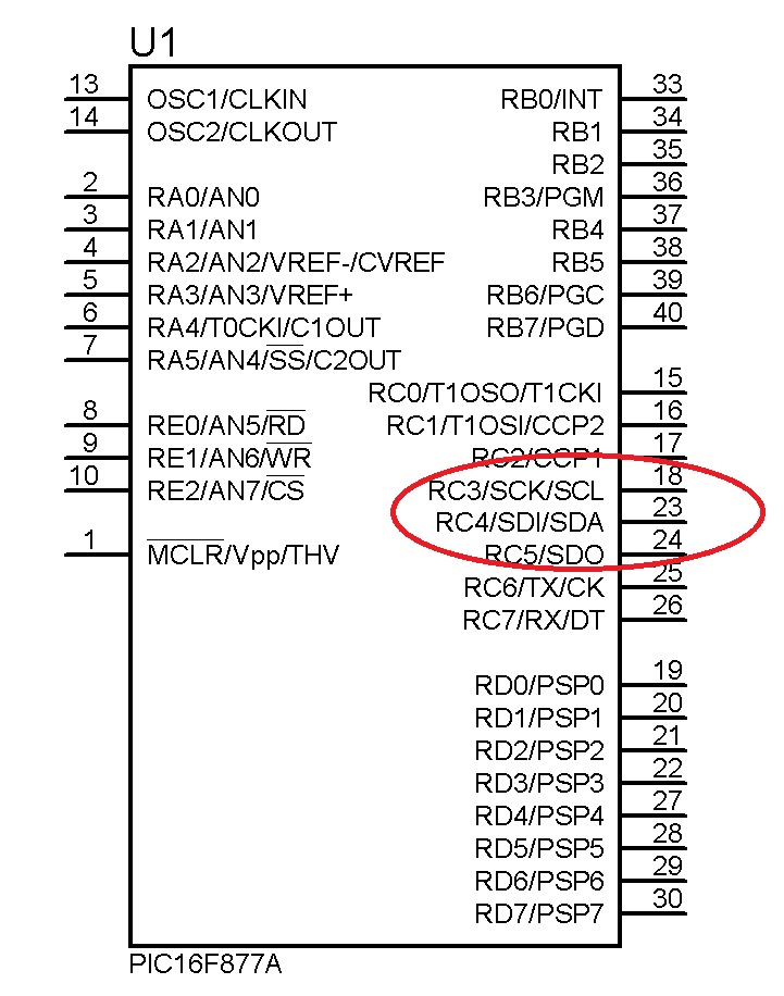
PIC
For PIC microcontrollers, specifically the PIC16F877A, the hardware SPI pins are at RC3, RC4 and RC5. Note that PICs use the terms SDO and SDI instead of MOSI and MISO.
Other PIC programming environment, like PicBasic Pro, has software SPI functions. You can use my SPI library if you prefer to use XC8.
Implementing SPI using PICs are discussed in another tutorial.
Further Reading
I hope I have helped you understand more about the SPI protocol. As you build more projects, you will encounter a lot of devices that use it.
See my other posts for examples of devices that uses SPI:
- Nokia 3310 LCD and PIC16F877A
- Using the microSD Breakout Board
- Using the 0.96" Tiny OLED Display with Arduino
- Arduino Nokia 3310 LCD Interfacing
- Arduino NRF24L01 Interfacing Tutorial
- Using RFID with Raspberry Pi Zero
The best way to learn microcontrollers is to build projects so start building!
[the_ad id="3059"]

