
Bluetooth is the most popular way of connecting an Arduino to a smartphone wirelessly. In this tutorial, we will create an Arduino-bluetooth interface and send messages from an Arduino to a smartphone and Arduino to a personal computer.
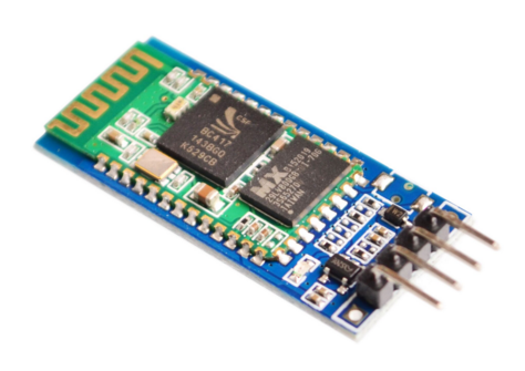
HC-05 Bluetooth Module
Bluetooth is a radio communication protocol that was created as a wireless alternative to the RS-232 serial protocol. Today, this technology is popular in connecting two or more mobile devices, particularly smartphones, tablets and laptop computers.
We’ll be using the HC-05 bluetooth module, a widely available and cheap bluetooth device that is capable of going into master (initiator) or slave (acceptor) device. There is another bluetooth module, the HC-06, which looks exactly like the HC-05. The primary difference between the two is that the HC-06 is a slave only device.
Here’s what my HC-05 module looks like:

Your device might have the KEY pin instead of the EN pin.
The HC-05 module has two modes: Data and Command mode. When in data mode, the module acts as a wireless bridge between two devices. The module is in data mode by default. The KEY pin, when pulled high (connected to 3.3V), is used to allow the HC-05 to enter AT Command mode. AT commands are used to configure the module. We will discuss these commands later.
For my device, AT Command mode is entered by keeping the button pressed and then powering up the module. There is still a KEY pin on my version but not readily accessible:

The EN pin, when pulled low (connected to ground), disables the module. The STATE pin is used to indicate connection status: it’s high when the module is connected to a device and low if not.
AT Command Mode
As mentioned, we enter command mode by either connecting the KEY to VCC or keeping the button pressed while powering on. The status LED will stay on for 1 second and stay off for another second if in AT Command mode.
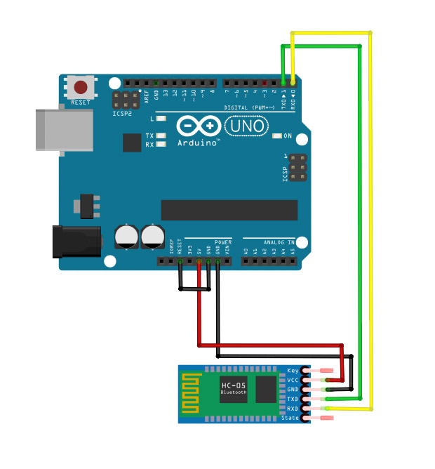
AT Commands are sent to the module serially using a USB-to-TTL cable or an Arduino. Choosing the latter, I connected the HC-05 tx pin to the Arduino UNO’s tx pin and its rx pin to the UNO’s rx pin just like in this tutorial.
Here’s the wiring diagram:
Because the Arduino will act like the USB-to-TTL converter and nothing else, we need to load an empty sketch to it. An empty sketch requires empty setup() and loop() functions:
void setup() {
}

void loop(){
}
Open the serial monitor and set the baud rate to 38400 and include both NL & CR. Here’s some commands you can use:
AT - test the connection. The module should respond with “OK”
AT+UART - see the baud rate, stop bit and parity bit. This specifies the baud rate used in command mode. AT+UART= <baud rate, stop bit (0 or 1), parity bit (0 or 1)> to set a new baud rate. The baud rate can be 1200, 2400, 4800, 9600, 19200, 38400, 57600 or 115200
AT+PSWD - view pin or AT+PSWD= <pin> to set a new pin
AT+ADDR - view device’s MAC address
AT+ROLE - view role (0 for slave, 1 for master). AT+ROLE= <0 or 1> to set new role.
AT+ORGL - restore factory settings
AT+VERSION - view device version
AT+STATE - view device state
AT+CMODE - set/view connection mode. 0 to connect the device to a specific address using AT+BIND. 1 to connect the device to any address.
AT+BIND=<mac address> - connect the device to a specific bluetooth address after AT+CMODE = 0.
View the complete set of AT Commands for the HC-05 Bluetooth module.
Control a LED via Bluetooth and Android
We don’t need to use AT commands to control a LED via bluetooth. We simply need to put the HC-05 module back to command mode and start sending data through it.
If your device is still in command mode, just remove the power and place it back. The device’s status LED will now start blinking rapidly to indicate that it is unconnected.
Next, we’ll need an Android app that can send serial commands via Bluetooth.
Sadly, there’s no such option for iPhone/iPad users because Apple requires every device to be accredited first before being usable and HC-05 is not accredited. You'll need a BLE module to work with iOS devices. I’ll write a separate tutorial for that in the nearest future.
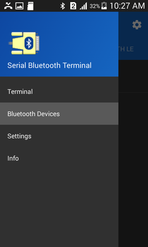
There are a number of bluetooth terminal application for android. I chose Serial Bluetooth Terminal.
Connect the app to the HC-05 module. The module’s status LED should now be steadily on.
Now we will write a sketch that accepts a character from the serial port (where the HC-05 is connected) and change the state of the LED based on that character. We will have a different wiring diagram for this one:

I went away from the hardware tx and rx pin so that we can still use the serial monitor for debugging. This means the HC-05 will be using the SoftwareSerial library.
 Buy Cheap HC-05 Modules at Aliexpress
Here’s how the sketch works: a “1” received on the software serial port will turn on the on-board LED. Conversely, a “0” turns the LED off. We print a message to the serial monitor for every event that occurs for easier debugging.
Here’s the full sketch:
#include <SoftwareSerial.h>
SoftwareSerial Bluetooth(10, 9); // RX, TX
int LED = 13; // the on-board LED
int Data; // the data received

void setup() {
  Bluetooth.begin(9600);
  Serial.begin(9600);
  Serial.println("Waiting for command...");
  Bluetooth.println("Send 1 to turn on the LED. Send 0 to turn Off");
  pinMode(LED,OUTPUT);

}

void loop() {
  if (Bluetooth.available()){ //wait for data received
    Data=Bluetooth.read();
    if(Data=='1'){
      digitalWrite(LED,1);
      Serial.println("LED On!");
      Bluetooth.println("LED On!");
    }
    else if(Data=='0'){
       digitalWrite(LED,0);
       Serial.println("LED Off!");
       Bluetooth.println("LED  On D13 Off ! ");
    }
    else{;}
  }
delay(100);
}
Open the Bluetooth Serial Monitor app. Select allow when asked about turning on Bluetooth. On the menu bar, select Bluetooth Devices:
Then select HC-05:

Go back to the menu bar and select Terminal. Reset your Arduino. If everything’s OK, this should be what’s on your screen:

Send “1” from the app and the LED on the board should turn on. Send “0” and it turns off.
Connect Arduino to PC via Bluetooth
We can also use the HC-05 bluetooth module to create a serial connection between the Arduino and a personal computer. You may need a bluetooth dongle if your PC doesn’t have bluetooth radio.
First, turn-on your computer’s bluetooth. You can go to PC Settings > Wireless:

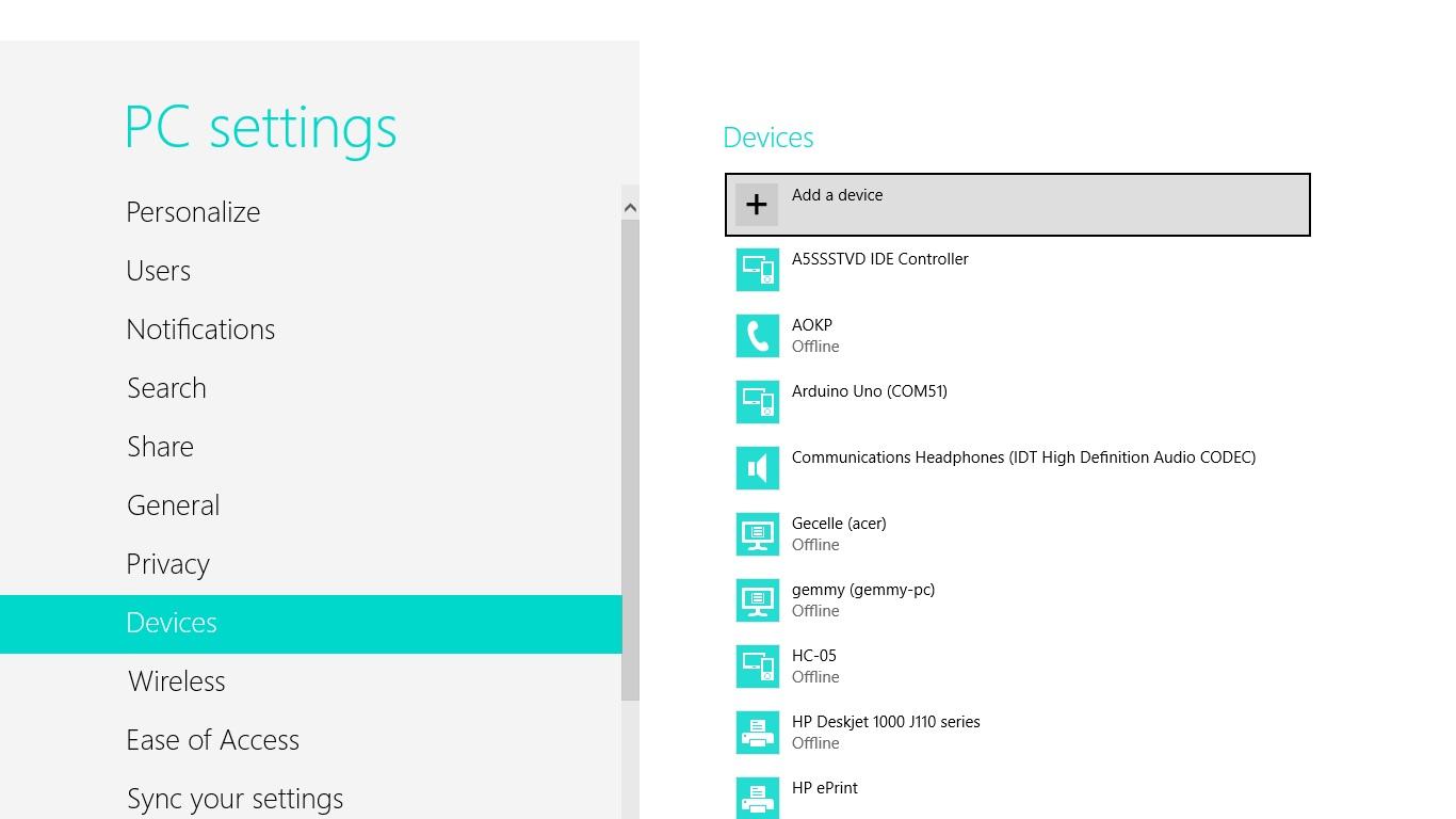
Then add the HC-05 as a bluetooth device via PC Settings > Devices:
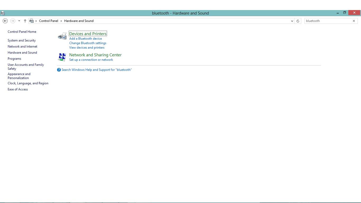
After that, open Bluetooth settings. This is not readily visible. To do this, go to Control Panel then Hardware and Sound. Type bluetooth on the search box:
Double-clicking “Change Bluetooth settings” will open a dialog box. On the Options tab of this dialog, check “Allow Bluetooth devices to find this computer”.

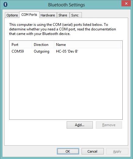
On the COM ports tab, click “Add”. Another dialog box will then appear. Click the Outgoing radio button and select HC-05 as the device that will use the COM port. Click OK. The HC-05 will now appear on the COM ports field:

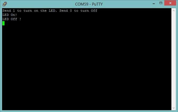
The COM port is now usable. Here’ its COM59. We can then now use Putty to communicate with the Arduino via bluetooth and issue the same commands we used in the android app:
Programming Arduino via Bluetooth
The cooler result of the step above is that you can now program your Arduino wirelessly! On the IDE, just select the Bluetooth COM port as your Arduino port (COM59 in our example) and upload a sketch just like how you would with a USB cable.

