

Electronics projects like movement and obstacle detection, drone fleet management, and robots require a camera for capturing images. I personally recommend using a Raspberry Pi or BeagleBone Black for these kind of projects because the Arduino doesn’t have enough juice to handle the complexities of pictures and, more so, videos. However, if the project doesn’t require a high resolution image then the OV7670 camera module might be for you. This arduino camera tutorial features such camera and how you can use it to capture VGA-sized pictures.
I managed to buy a OV7670 camera module that looks like this:
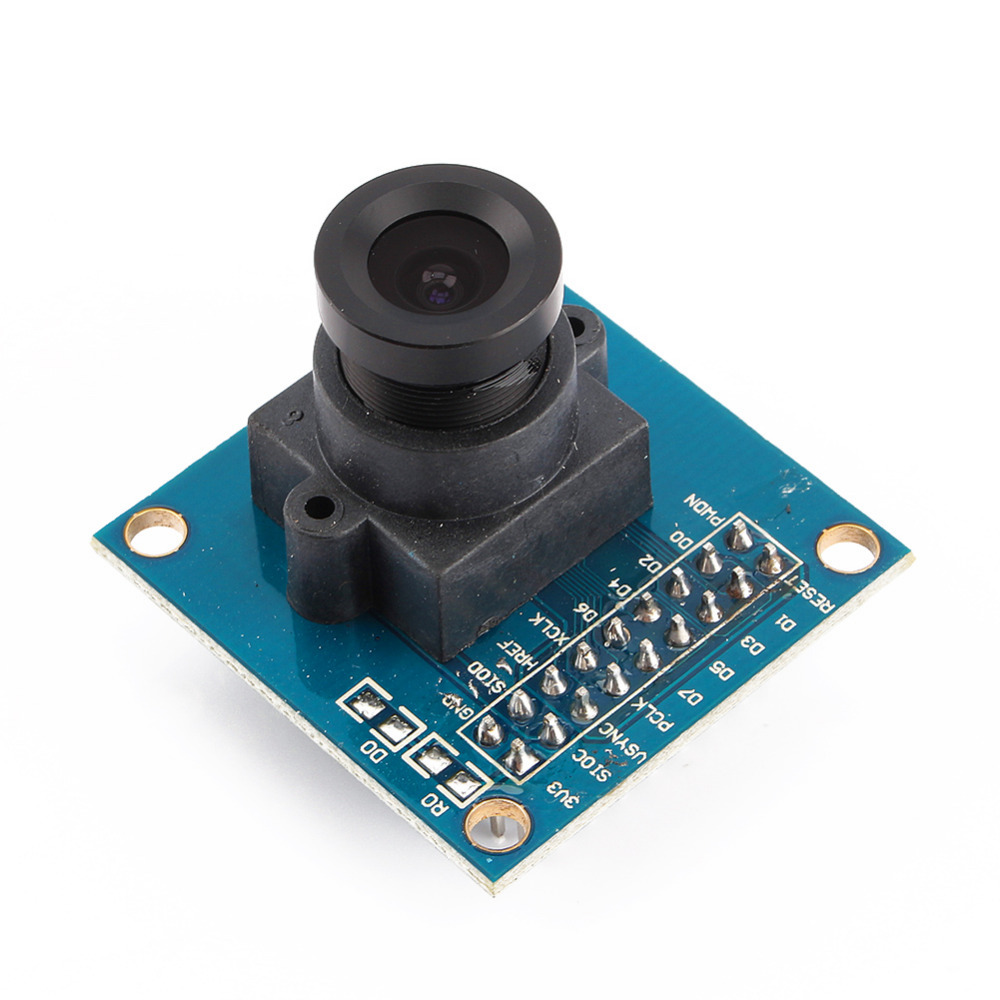
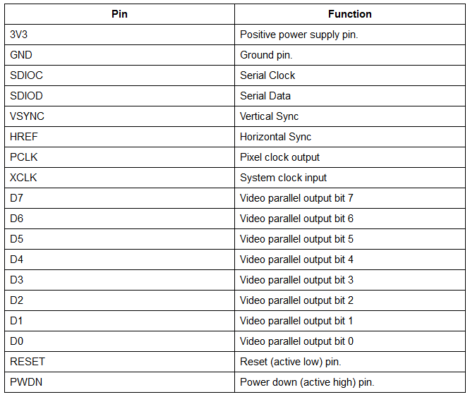
As you can see, the module has 18 output pins with the following functions:
Some modules contain 16 pins; these lack the RESET and PWON pins. Since I own the 18-pin OV7670 module, the rest of the tutorial will be based on such module.
If you noticed, the OV7670 camera module has a serial data and clock pin. This means that the Arduino can communicate with the module using I2C. Also, the module operates on 3.3 V so if we are to send data to the OV7670 from the Arduino, we must use a voltage divider to bring the level down.
Here is a common wiring diagram used to build an Arduino camera using the OV7670 camera module:
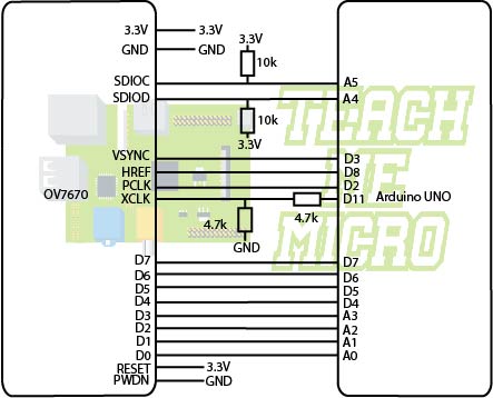
Note that there is no efficient way for the Arduino to display the captured image. What it only does is command the module to take a picture, acquire the image and then send it to a computer via the Arduino’s USB port. Thus, you need to have another application that will display the image from the USB port to your desktop computer.
Here is a code to be used to capture an image using the Arduino and OV7670 camera module:
#define F_CPU 16000000UL
#include <stdint.h>
#include <avr/io.h>
#include <avr/interrupt.h>
#include <util/twi.h>
#include <util/delay.h>
#include <avr/pgmspace.h>
#include "ov7670.h"
/* Configuration: this lets you easily change between different resolutions
* You must only uncomment one
* no more no less*/
#define useVga
//#define useQvga
//#define useQqvga

static inline void serialWrB(uint8_t dat){
        while(!( UCSR0A & (1<<UDRE0)));//wait for byte to transmit
        UDR0=dat;
        while(!( UCSR0A & (1<<UDRE0)));//wait for byte to transmit
}
static void StringPgm(const char * str){
        do{
                serialWrB(pgm_read_byte_near(str));
        }while(pgm_read_byte_near(++str));
}
static void captureImg(uint16_t wg,uint16_t hg){
        uint16_t lg2;
#ifdef useQvga
        uint8_t buf[640];
#elif defined(useQqvga)
        uint8_t buf[320];
#endif
        StringPgm(PSTR("RDY"));
        //Wait for vsync it is on pin 3 (counting from 0) portD
        while(!(PIND&8));//wait for high
        while((PIND&8));//wait for low
#ifdef useVga
        while(hg--){
                lg2=wg;
                while(lg2--){
                        while((PIND&4));//wait for low
                        UDR0=(PINC&15)|(PIND&240);
                        while(!(PIND&4));//wait for high
                }
        }
#elif defined(useQvga)
        /*We send half of the line while reading then half later */
        while(hg--){
                uint8_t*b=buf,*b2=buf;
                lg2=wg/2;
                while(lg2--){
                        while((PIND&4));//wait for low
                        *b++=(PINC&15)|(PIND&240);
                        while(!(PIND&4));//wait for high
                        while((PIND&4));//wait for low
                        *b++=(PINC&15)|(PIND&240);
                        UDR0=*b2++;
                        while(!(PIND&4));//wait for high
                }
                /* Finish sending the remainder during blanking */
                lg2=wg/2;
                while(!( UCSR0A & (1<<UDRE0)));//wait for byte to transmit
                while(lg2--){
                        UDR0=*b2++;
                        while(!( UCSR0A & (1<<UDRE0)));//wait for byte to transmit
                }
        }
#else
        /* This code is very similar to qvga sending code except we have even more blanking time to take advantage of */
        while(hg--){
                uint8_t*b=buf,*b2=buf;
                lg2=wg/5;
                while(lg2--){
                        while((PIND&4));//wait for low
                        *b++=(PINC&15)|(PIND&240);
                        while(!(PIND&4));//wait for high
                        while((PIND&4));//wait for low
                        *b++=(PINC&15)|(PIND&240);
                        while(!(PIND&4));//wait for high
                        while((PIND&4));//wait for low
                        *b++=(PINC&15)|(PIND&240);
                        while(!(PIND&4));//wait for high
                        while((PIND&4));//wait for low
                        *b++=(PINC&15)|(PIND&240);
                        while(!(PIND&4));//wait for high
                        while((PIND&4));//wait for low
                        *b++=(PINC&15)|(PIND&240);
                        UDR0=*b2++;
                        while(!(PIND&4));//wait for high
                }
                /* Finish sending the remainder during blanking */
                lg2=320-(wg/5);
                while(!( UCSR0A & (1<<UDRE0)));//wait for byte to transmit
                while(lg2--){
                        UDR0=*b2++;
                        while(!( UCSR0A & (1<<UDRE0)));//wait for byte to transmit
                }
        }
#endif
}
int main(void){
        cli();//disable interrupts
        /* Setup the 8mhz PWM clock
         * This will be on pin 11*/
        DDRB|=(1<<3);//pin 11
        ASSR &= ~(_BV(EXCLK) | _BV(AS2));
        TCCR2A=(1<<COM2A0)|(1<<WGM21)|(1<<WGM20);
        TCCR2B=(1<<WGM22)|(1<<CS20);
        OCR2A=0;//(F_CPU)/(2*(X+1))
        DDRC&=~15;//low d0-d3 camera
        DDRD&=~252;//d7-d4 and interrupt pins
        _delay_ms(3000);
        //set up twi for 100khz
        TWSR&=~3;//disable prescaler for TWI
        TWBR=72;//set to 100khz
        //enable serial
        UBRR0H=0;
        UBRR0L=1;//0 = 2M baud rate. 1 = 1M baud. 3 = 0.5M. 7 = 250k 207 is 9600 baud rate.
        UCSR0A|=2;//double speed aysnc
        UCSR0B = (1<<RXEN0)|(1<<TXEN0);//Enable receiver and transmitter
        UCSR0C=6;//async 1 stop bit 8bit char no parity bits
        camInit();
#ifdef useVga
        setRes(VGA);
        setColorSpace(BAYER_RGB);
        wrReg(0x11,25);
#elif defined(useQvga)
        setRes(QVGA);
        setColorSpace(YUV422);
        wrReg(0x11,12);
#else
        setRes(QQVGA);
        setColorSpace(YUV422);
        wrReg(0x11,3);
#endif
        /* If you are not sure what value to use here for the divider (register 0x11)
         * Values I have found to work raw vga 25 qqvga yuv422 12 qvga yuv422 21
         * run the commented out test below and pick the smallest value that gets a correct image */
        while (1){
                /* captureImg operates in bytes not pixels in some cases pixels are two bytes per pixel
                 * So for the width (if you were reading 640x480) you would put 1280 if you are reading yuv422 or rgb565 */
                /*uint8_t x=63;//Uncomment this block to test divider settings note the other line you need to uncomment
                  do{
                  wrReg(0x11,x);
                  _delay_ms(1000);*/
#ifdef useVga
                captureImg(640,480);
#elif defined(useQvga)
                captureImg(320*2,240);
#else
                captureImg(160*2,120);
#endif
                //}while(--x);//Uncomment this line to test divider settings
        }
}
Note that this code requires the ov7670 library which was originally done by ComputerNerd. Download the library on this repository.
Next, we need a desktop application that will read the image data from the Arduino’s USB port and display it on screen. Download this C/C++ package and run it using G++ for Linux or DevC++ for Windows. Unfortunately, C/C++ programming on desktop computers is beyond the scope of this tutorial so I can’t help you with this further.
Hopefully I’ve helped you in setting up the OV7670 camera module with the Arduino UNO. However, I would still recommend you use more advanced boards like Raspberry Pi or BeagleBone Black to handle images as the Arduino UNO is simply not powerful enough. Check out my tutorial on using a web camera with the Raspberry Pi and create cool projects!

