
In general terms, a magnetometer measures the magnetism of objects or places. In fact, a compass is a type of magnetometer. This project demonstrates how to use the HMC5883L magnetometer IC as a compass with an Arduino microcontroller.
Hardware Setup
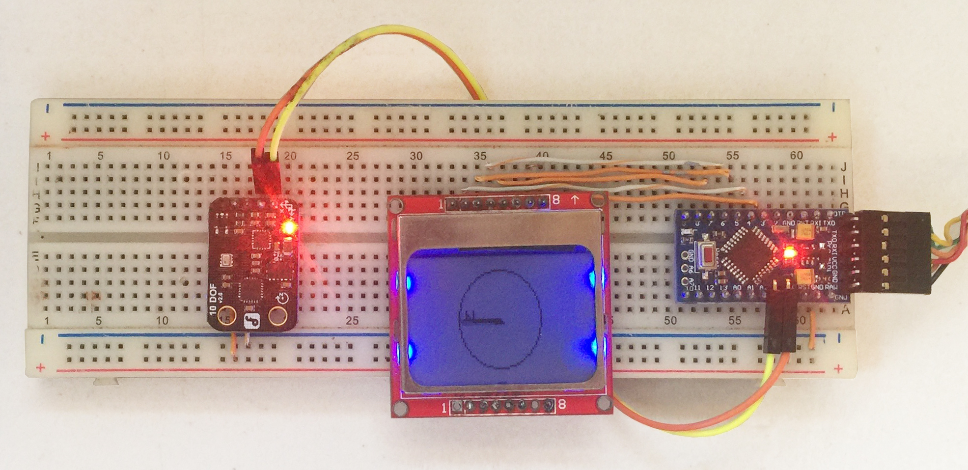
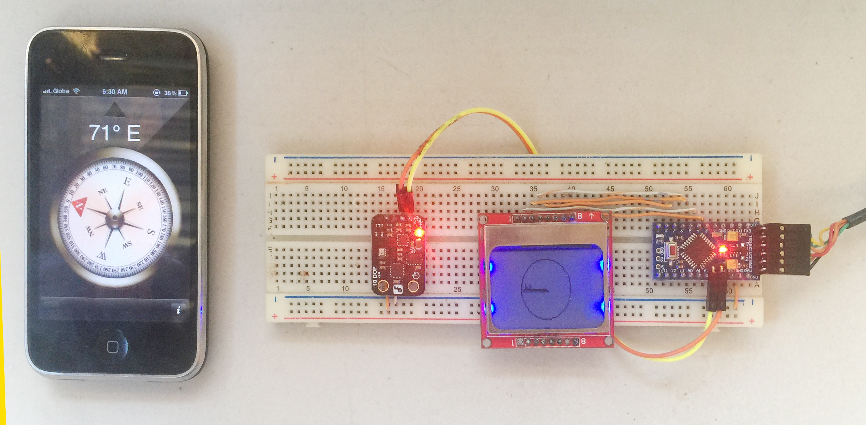
I have setup this project on a mini breadboard using the parts:
- HMC5883L Magnetometer
- Nokia 3310/5110 LCD Breakout Board
- Arduino Pro Mini 5V
The HMC5883L magnetometer is fairly common but for this project, I used the 10 DOF IMU from DFRobot. This module contains not only the HMC5883L but also a BMP280 barometric pressure sensor, ITG-3205 gyroscope and ADXL345 accelerometer into one device. Note that the ordinary HMC5883L magnetometer module will still work with this project. Moreover, the Nokia 3310/5110 LCD is used for display and the Arduino Pro Mini is the brains of the project.
Needed Libraries
For this project's sketch to run, you'll need the following libraries:
You can learn more about using the Nokia 3310/5110 LCD and its libraries in a separate article.
Developing the Project
Wiring
The project is not that hard because of the readily available libraries. The wiring is also straightforward:
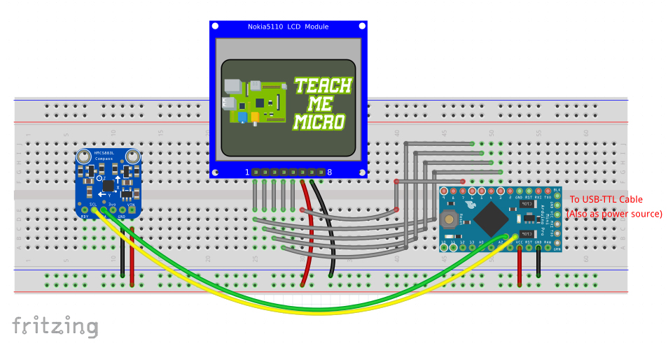
Nokia LCD to Pro Mini Connection:
| Nokia 3310 LCD | Arduino Pro Mini |
|---|---|
| 1 (RST) | D3 |
| 2 (CE) | D4 |
| 3 (DC) | D5 |
| 4 (DIN) | D6 |
| 5 (CLK) | D7 |
| 6 (VCC) | VCC |
| 7 (LIGHT) | GND |
| 8 (GND) | GND |
HMC5883L to Pro Mini Connection:
| HMC5883L | Arduino Pro Mini |
|---|---|
| SCL | A5 |
| SDA | A4 |
| VIN | VCC |
| GND | GND |
Reading Data from HMC5883L
The first step was to make sure the HMC5883L is giving out the correct heading. According to the example provided in the HMC5883L library, the range, measurement mode, data rate and samples must be set before reading out data from the magnetometer. Thus, I created this function:
void initCompass(){
 while (!compass.begin()) {
  Serial.println("Could not find a valid QMC5883 sensor, check wiring!");
  delay(500);
 }

 Serial.println("Initialize QMC5883");
 compass.setRange(QMC5883_RANGE_2GA);
 compass.setMeasurementMode(QMC5883_CONTINOUS);
 compass.setDataRate(QMC5883_DATARATE_50HZ);
 compass.setSamples(QMC5883_SAMPLES_8);
}
The library has a neat begin() function which checks out if the sensor is connected or not, which I used as seen above.
Correcting for Magnetic Declination
Heading is the term used to measure your position from the north pole. North pole is actually the north geographic pole while compasses detect the north magnetic pole which is a different place although not that far from the other north pole. The distance between each pole is really not the issue; it's the magnetic declination between the two. Thus, there's a need to correct for this declination but first you must find out your area's declination through here.
For example, the magnetic declination in our area is - 0° 53' (negative 0 degrees and 53' minutes). This declination must be converted into radians:
Let's say the reading of the compass is 2.0 radians. The correct heading, accounting declination, is now:
Drawing the Compass
Now that I have the correct heading, the next part is to display that heading on the LCD. Showing the heading as a number is too easy; I wanted an arrow that will always point to the north like a real compass.
The GFX library I pointed out above has a line function:
drawLine(uint16_t x0, uint16_t y0, uint16_t x1, uint16_t, y1, uint16_t color);Here, the x0, y0 are the coordinates of the origin of the line while x1, y1 are those of the end point.
Specifying the origin of the arrow for the compass is just writing the center of the LCD which is (41, 23). The end point of the line is based on the heading. To illustrate:
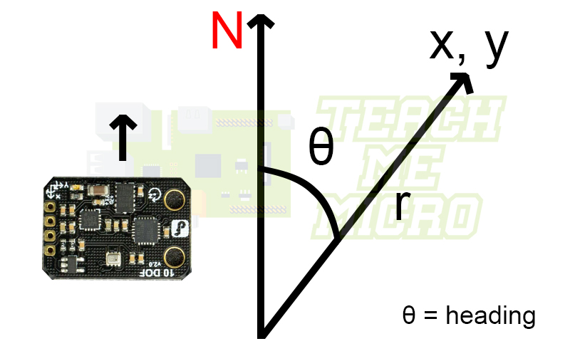
The end point could be computed as:
In geometry, coordinate (0,0) is at the center. But here, our center is at (41, 23) thus the axes must be translated. Moreover, I wanted to draw the North line, not the heading line. Finally, the direction of the arrow must be corrected according to how the HMC5883L board is connected to my breadboard.
Full Sketch
Here is now the full Arduino Sketch for this project:
#include <SPI.h>
#include <Wire.h>
#include <DFRobot_QMC5883.h>
#include <Adafruit_GFX.h>
#include <Adafruit_PCD8544.h>

// Software SPI (slower updates, more flexible pin options):
// pin 7 - Serial clock out (SCLK)
// pin 6 - Serial data out (DIN)
// pin 5 - Data/Command select (D/C)
// pin 4 - LCD chip select (CS)
// pin 3 - LCD reset (RST)
Adafruit_PCD8544 display = Adafruit_PCD8544(7, 6, 5, 4, 3);

DFRobot_QMC5883 compass;

float arrDirection;
uint16_t centerX = 41;
uint16_t centerY = 23;
float endX;
float endY;
float hyp = 23;
float sum;

#define SAMPLE_SIZE 3

void setup()   {
  Serial.begin(9600);
  initDisplay();

  display.println("Make figure");
  display.println("8's to calibrate sensor");
  display.display();
  initCompass();
  delay(5000);
  display.clearDisplay();

}

void initCompass(){
  while (!compass.begin())
  {
    Serial.println("Could not find a valid QMC5883 sensor, check wiring!");
    delay(500);
  }
  Serial.println("Initialize QMC5883");
  compass.setRange(QMC5883_RANGE_2GA);
  compass.setMeasurementMode(QMC5883_CONTINOUS);
  compass.setDataRate(QMC5883_DATARATE_50HZ);
  compass.setSamples(QMC5883_SAMPLES_8);
}

void initDisplay(){
  display.begin();

  display.setContrast(50);

  display.display(); // show splashscreen
  delay(2000);
  display.clearDisplay();   // clears the screen and buffer

  display.setTextSize(1);
  display.setTextColor(BLACK);
  display.setCursor(0,0);
}

float calcPosition(){

  for (int i=0;i<SAMPLE_SIZE;i++){
   Vector norm = compass.readNormalize();

   // Calculate heading
   float heading = atan2(norm.YAxis, norm.XAxis);
   //Calculate magnetic declination according to your location
   //See http://magnetic-declination.com
   float declinationAngle = (0.0 + (53.0 / 60.0)) / (180 / PI);
   heading -= declinationAngle;

   // Correct for heading < 0deg and heading > 360deg
   if (heading < 0){
     heading += 2 * PI;
   }

   if (heading > 2 * PI){
     heading -= 2 * PI;
   }
   sum += heading;
  }

  float output = sum/SAMPLE_SIZE;
  sum = 0;
  float outDegrees = output*180/PI;

  Serial.println(outDegrees);

  return output;

}

void loop() {

   display.drawCircle(centerX, centerY, 23, BLACK);
   endX = 41 - (hyp * sin(calcPosition()-PI/2));
   endY = 23 - (hyp * cos(calcPosition()-PI/2));

   display.drawLine(centerX, centerY, endX, endY, BLACK);
   display.drawLine(centerX+1, centerY+1, endX+1, endY+1, BLACK);
   display.drawLine(centerX+2, centerY+2, endX+2, endY+2, BLACK);
   display.setCursor(endX + 4, endY - 4);
   display.println("N");
   display.display();
   delay(500);
   display.clearDisplay();
}
Here you can see how I calculated the heading in degrees accounting magnetic declination and how I drew a line that always point north. I had to make the line thicker so I needed to draw the line three times with each coordinates incremented by a pixel. Also, I drew a circle to make it more compass-like.
Video
Here's the demonstration of the project:
Note that the HMC5833L must be calibrated before acquiring a more stable data. To calibrate, make figure 8's with the device.
That's it! Feel free to comment if you have any questions about this project. Happy building!

