
Current sensors can have different applications: power supplies, over-current protection, and motor control to name a few. In this Arduino current sensor tutorial, we will look at how to read current using the ACS712 sensor.
The ACS712 Current Sensor
The ACS712 contains a hall effect sensor that converts its input current to a magnetic field. The strength of this magnetic field gets stronger as the current gets higher. As we discussed in this article, hall effect is a phenomena when a voltage exists on a current-carrying conductor due to the presence of a magnetic field. This means that the ACS712 follows the same concept: current to magnetic field to voltage.

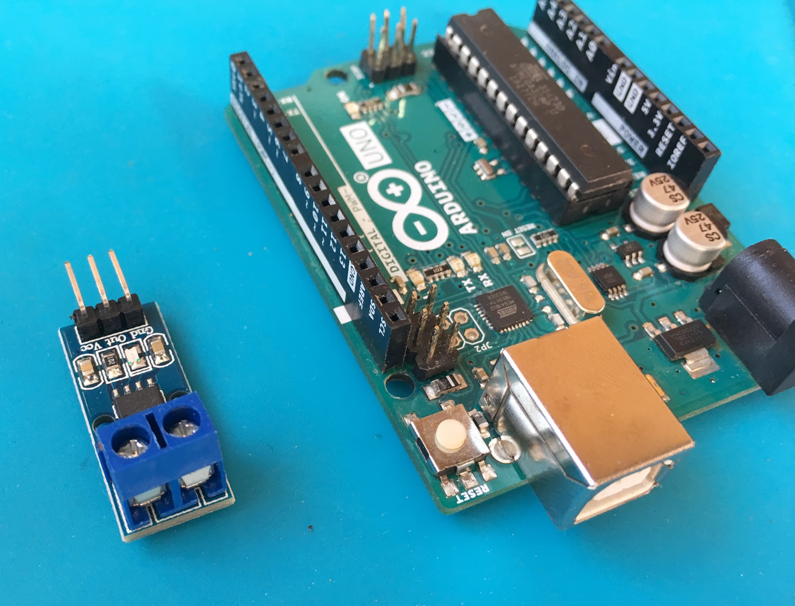
The module shown contains just three output pins:
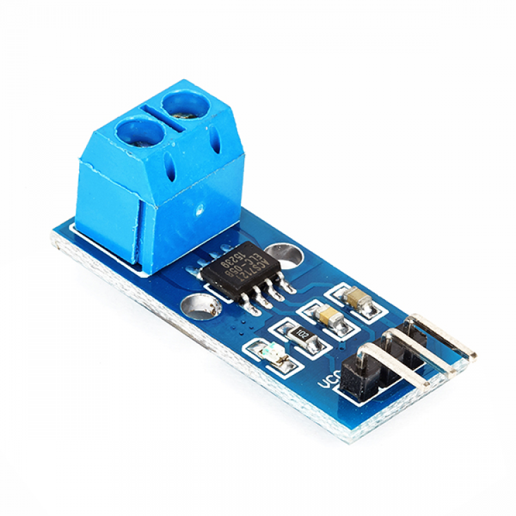
The VCC pin can receive up to 8 V but ideally should be only 5 V. The OUT pin produces a voltage proportional to the current read in the input terminals. When no current is read, the OUT pin gives out a voltage that is half of VCC.
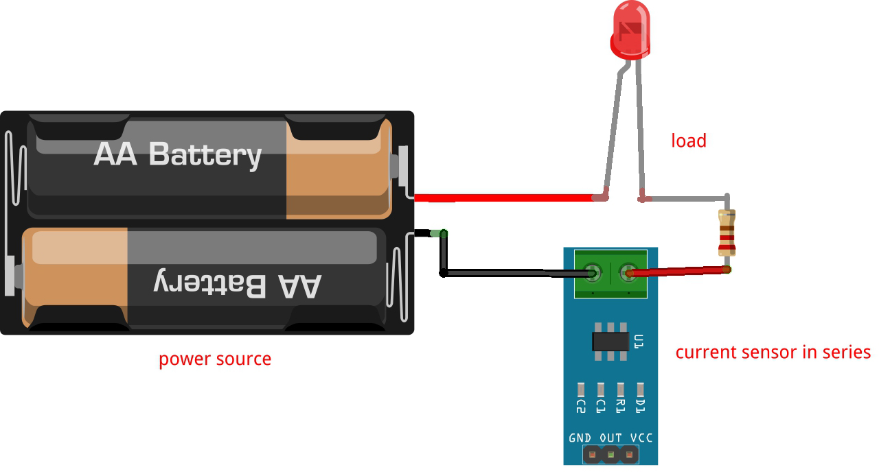
The current to be measured is inserted into the screw terminals. Similar to connecting ammeters, the current sensor must be connected in series.
Converting the output voltage from the sensor to current is straightforward. According to the datasheet:
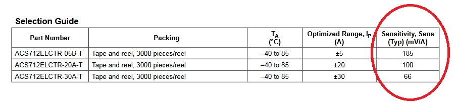
It turns out, there are three versions of the ACS712. The module I own features the ACS712ELCTR-05B-T. The number at the end (05) indicates that this sensor can read from -5 to 5 A.
The table says that the sensitivity of this type is 185 mV/A. Thus, to get the current reading, we use the formula
Where V is the voltage from the OUT pin of the sensor. Note that the current in this formula will be in kilo amperes.
Building an Arduino Current Sensor
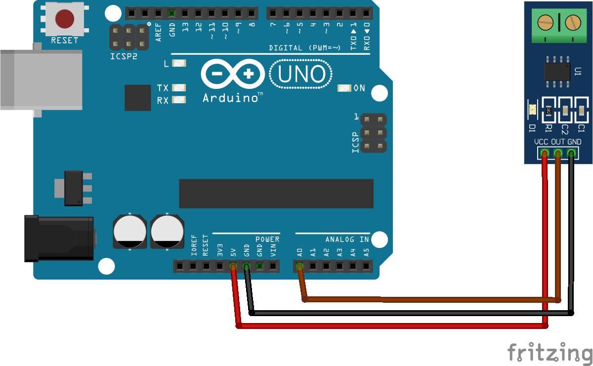
The ACS712 connects directly to any Arduino board. Its VCC pin connects to the 5 V pin of the Arduino, GND pin to GND and the OUT pin connects to the A0 pin.
To test if the sensor is working, upload the AnalogReadSerial sketch (File > Examples > Basics) to your Arduino. When there is no current, the serial monitor should display a value of around 512 --- 2.5 V for a 10-bit ADC.
The sketch below converts the voltage output from the sensor to current. The serial monitor shows the current reading:
/*
  Arduino Current Sensor using ACS712 Module
  by Roland Pelayo

*/

//Change this value to get more stable result but may slow down Arduino
#define SAMPLES 10

float average_current;

void setup() {
  // initialize serial communication at 9600 bits per second:
  Serial.begin(9600);
}

void loop() {
  for(int i=0;i<SAMPLES;i++){
    // read the input on analog pin 0:
    int sensorValue = analogRead(A0);
    //convert to voltage
    float volt = sensorValue * 5;
    volt = volt / 1023;
    //convert to current
    float current = volt / 185;
    //convert to Amps
    current = current / 1000;
    average_current += current;
    delay(1); //1 millisecond delay for stability
  }
  average_current = average_current / SAMPLES;
  // print out the current to serial monitor
  Serial.print("Current: ");
  Serial.println(average_current);
  delay(100); //just a small delay
}
In this sketch, I accumulate the current readings and take their average. Doing this leads to a stabler output.
First, the voltage from the sensor is read through Arduino's ADC:
int sensorValue = analogRead(A0);
The integer sensorValue could be anything between 0 and 1023. This equates to 1024 levels from the 10-bit ADC equation:
![]()
To convert sensorValue to voltage, we divide it to 1023 and then multiply the results to the maximum allowed voltage (5 V).
float volt = sensorValue * 5;
volt = volt / 1023;
Then as mentioned, the sensitivity of the sensor is 185 mV per A. Thus, to acquire current from the voltage reading, we divide the voltage by 185:
float current = volt / 185;
This will give us a current in kilo amperes since the sensitivity is in millivolts. The current in amperes then is:
current = current / 1000;
We add this value to the accumulator so that we may take the average later on for a much more stable output:
average_current += current;
...
 average_current = average_current / SAMPLES;
SAMPLES in the code has a value of 10. A higher SAMPLES value will produce a cleaner output but may slow down the Arduino.
To view the results of the code, just open the Serial Monitor after uploading.
I hope this tutorial helps you in any way. For questions or clarifications, kindly drop a comment below!

