
The classic parallel LCD sometimes poses a problem for projects that use a lot of Arduino pins. The least amount of pins you can use is six, excluding the power pins and the potentiometer contrast adjust (optional) pin. Thankfully, by using an I2C LCD "backpack", the pin use can be reduced to four!
I2C LCD Backpack
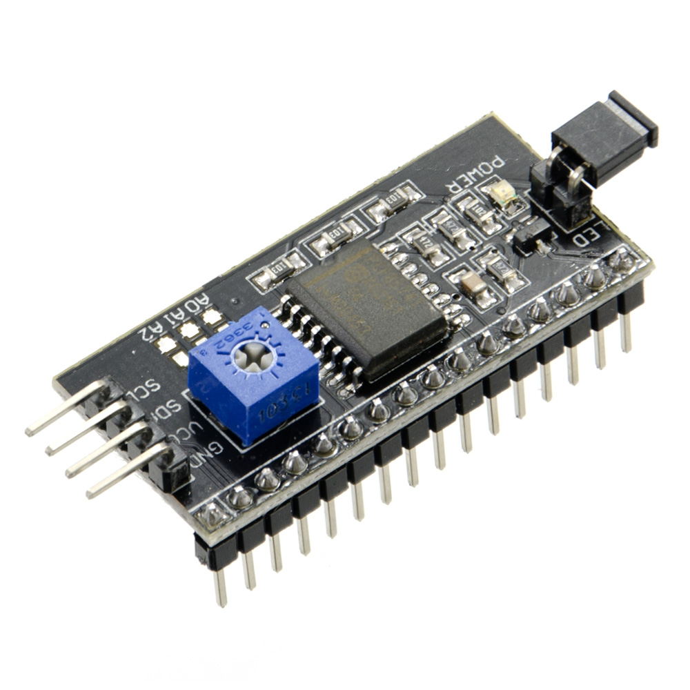
This is the I2C LCD "backpack" I was referring to:

At the center of the board is the PCF8547 controller by NXP. The row of pins is attached to the same row of pins on any HD44870-compatible LCD. The four pins on the side are the one you'll attach to the Arduino or any I2C-supported microcontroller.
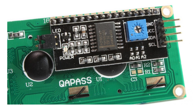
This is how the backpack looks like attached to a LCD:
Now let's look at the backpack in detail:

- A trimmer is already attached to the board which acts as the contrast adjust. No more bulky potentiometers!
- The jumper enables/disables the backlight. Remove the jumper to disable the backlight.
- Some backpacks come with PCF8574T while some come with PCF8574AT. Each of this chips have their own I2C address! PCF84574T uses 0x27 while PCF8457AT uses 0x3F. These addresses are used in the sketch so they're kinda important to know.
- You can, in fact, change the I2C address via the I2C Address Set pads on the board. A0, A1, A2 represent three bits that would be subtracted from the address. By default, each of these pads are connected to VDD or the positive supply. Soldering them connects them to GND. For example, if you were to solder pad A0, the address becomes 0x26 because 0x27 - (A2 + A1 - A0) = 0x27 - (001)2 = 0x26. If you were to solder A0 and A1 then the address becomes 0x24 because 0x27 - (A2 + A1 + A0) = 0x27 - (011)2 = 0x24.
- Changing the I2C address is necessary if you have multiple LCDs with the same backpack.
Using the I2C LCD with Arduino
For using with an Arduino, we'll need the LiquidCrystal_I2C library. Here's an example sketch which is found in File -> Examples -> LiquidCrystal_I2C -> HelloWorld:
#include <Wire.h>
#include <LiquidCrystal_I2C.h>

// Set the LCD address to 0x27 for a 16 chars and 2 line display
LiquidCrystal_I2C lcd(0x27, 16, 2);

void setup()
{
	// initialize the LCD
	lcd.begin();

	// Turn on the blacklight and print a message.
	lcd.backlight();
	lcd.print("Hello, world!");
}

void loop()
{
	// Do nothing here...
}
The command to write a text on the LCD is the same as the original one:
lcd.print("Hello, world!");
Noticed before this line, we have this:
lcd.backlight();
It's a way to enable/disable the backlight through code which is not part of the original LiquidCrystal library.
Also, here's how to initialize the I2C LCD object:
LiquidCrystal_I2C lcd(0x27, 16, 2);
The first parameter is the I2C address, the second is the number of columns and the last number is the number of rows. The library can be used with other LCD sizes as long as the controller is HD44870.
Custom characters is also supported. Here's another example sketch from the library (File -> Examples -> LiquidCrystal_I2C -> CustomChars:
#include <Wire.h>
#include <LiquidCrystal_I2C.h>

uint8_t bell[8]  = {0x4, 0xe, 0xe, 0xe, 0x1f, 0x0, 0x4};
uint8_t note[8]  = {0x2, 0x3, 0x2, 0xe, 0x1e, 0xc, 0x0};
uint8_t clock[8] = {0x0, 0xe, 0x15, 0x17, 0x11, 0xe, 0x0};
uint8_t heart[8] = {0x0, 0xa, 0x1f, 0x1f, 0xe, 0x4, 0x0};
uint8_t duck[8]  = {0x0, 0xc, 0x1d, 0xf, 0xf, 0x6, 0x0};
uint8_t check[8] = {0x0, 0x1 ,0x3, 0x16, 0x1c, 0x8, 0x0};
uint8_t cross[8] = {0x0, 0x1b, 0xe, 0x4, 0xe, 0x1b, 0x0};
uint8_t retarrow[8] = {	0x1, 0x1, 0x5, 0x9, 0x1f, 0x8, 0x4};

// Set the LCD address to 0x27 for a 16 chars and 2 line display
LiquidCrystal_I2C lcd(0x27, 16, 2);

void setup()
{
	lcd.begin();
	lcd.backlight();

	lcd.createChar(0, bell);
	lcd.createChar(1, note);
	lcd.createChar(2, clock);
	lcd.createChar(3, heart);
	lcd.createChar(4, duck);
	lcd.createChar(5, check);
	lcd.createChar(6, cross);
	lcd.createChar(7, retarrow);
	lcd.home();

	lcd.print("Hello world...");
	lcd.setCursor(0, 1);
	lcd.print(" i ");
	lcd.write(3);
	lcd.print(" arduinos!");
	delay(5000);
	displayKeyCodes();
}

// display all keycodes
void displayKeyCodes(void) {
	uint8_t i = 0;

	while (1) {
		lcd.clear();
		lcd.print("Codes 0x");
		lcd.print(i, HEX);
		lcd.print("-0x");
		lcd.print(i + 16, HEX);
		lcd.setCursor(0, 1);

		for (int j = 0; j < 16; j++) {
			lcd.write(i + j);
		}
		i += 16;

		delay(4000);
	}
}

void loop()
{
	// Do nothing here...
}
Video
Here's the LCD with the backpack in action:
So far I'm really liking this I2C LCD backpack as it reduces the number of wires I have to use. If you're also having problem with the pin count of a common parallel LCD, then you should try this one.

