
An interrupt, in microcontroller context, is a signal that temporarily stops what the CPU is currently working at. Programming using interrupts is very different from the usual top-to-bottom sequence in an Arduino program and thus can be confusing for some. This article aims to introduce how an interrupt works and how you can use it to your advantage. Also, if you are looking to create multi-tasking programs, then this Arduino Interrupt tutorial is a must read for you.
Arduino Interrupt Introduction
A typical Arduino sketch consists of setup() and loop() functions:
void setup(){
}

void loop(){
}
When a sketch is executed, the top most lines are run first. So logically the setup() function is run before the loop() function. Although it’s far more common to have headers for libraries above setup() which are of course catered first by the compiler. The loop() function is an endless loop so there is no way to exit it.
If we will now use interrupts, we add a third function named isr(). ISR is short for Interrupt Service Routine. This is where the program jumps to whenever there is an interrupt.
void setup(){
}

void loop(){
}

void isr(){
}
When does the program jump to isr()? For the Arduino platform, there will be an interrupt when specific pins change their state. So let’s say the interrupt pin is normally high, when it becomes low, then the interrupt is triggered and the program jumps to isr().
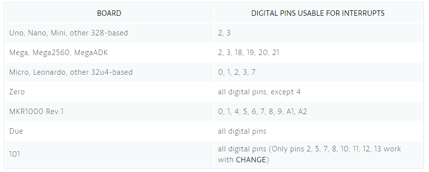
These external interrupt pins are different for each Arduino model:
Here is an example code that uses interrupt programming for controlling a LED:
const byte ledPin = 13;
const byte interruptPin = 2;
volatile byte state = LOW;

void setup() {
   pinMode(ledPin, OUTPUT);
   pinMode(interruptPin, INPUT_PULLUP);
   attachInterrupt(digitalPinToInterrupt(interruptPin), blink, CHANGE);
}

void loop() {
   digitalWrite(ledPin, state);
}

void blink() {
   state = !state;
}
Basically, a button is attached to an interrupt pin. Whenever the button is pressed, the interrupt pin changes its state and triggers the interrupt. If the button is not pressed, the program stays on the loop() function.
The interrupt service routine is named blink() in this case and contains a one-line code that toggles the state of the LED pin.
Here the interrupt pin is D2 and is given the name interruptPin. Just like any input pin, the interruptPin must be declared using pinMode()
pinMode(interruptPin, INPUT_PULLUP);
We used the INPUT_PULLUP option so that we can skip adding a pull-up resistor to the button.
Next, we attach the interrupt using the attachInterrupt() function:
attachInterrupt(digitalPinToInterrupt(interruptPin), blink, CHANGE);
The attachInterrupt() function has three parameters: first is the interrupt pin converted to Interrupt using the digitalPinToInterrupt() function, second is the isr function named blink, and last is the mode which describes when the interrupt is triggered. Here, it’s set to CHANGE which means the interrupt is triggered when the pin changes its state. Other possible options are:
- LOW to trigger the interrupt whenever the pin is low
- RISING to trigger when the pin goes from low to high
- FALLING for when the pin goes from high to low
For ARM-based Arduinos (Due, Zero, MKR1000), this is a possible option:
- HIGH to trigger the interrupt whenever the pin is high
Now you might ask: isn't the above sketch the same as using digitalRead() inside loop()?
Well, when using digitalRead() to read the state of the button, you must press the button at the right time so that the Arduino can capture it. This might not matter when the only thing inside your loop() is reading the button's state. But when you have a lot of things going on, the Arduino might miss the button press.
When using interrupts, it doesn't matter when you press the button because the Arduino will detect it.
Pin Change Interrupt
Now there will be cases where two interrupt pins are not enough. Luckily, there is another type of interrupt that we can use on all Arduino pins: pin change interrupt. However, this method is not embedded into the Arduino platform and so we need to dig deeper into AVR programming.
For this tutorial, we will limit ourselves to ATMega328p powered boards like the Arduino UNO and Arduino Nano. Pin change interrupt for other boards will be covered (hopefully) in future tutorials.
We’ll look at the ATMega328p:
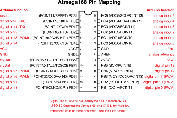
Notice that almost all pins have PCINT functions on them? PCINT is short for pin change interrupt and it covers all pins from D0 to D13 and A0 to A5.
However, there are only three possible interrupt vectors and consequently, three ISRs for all those pins. This means any pin change between D8 to D13 can trigger only one interrupt. This is also true for A0 to A5 and D0 to D7.
To enable pin change interrupt on a pin, we’ll need to manipulate the PCICR register:
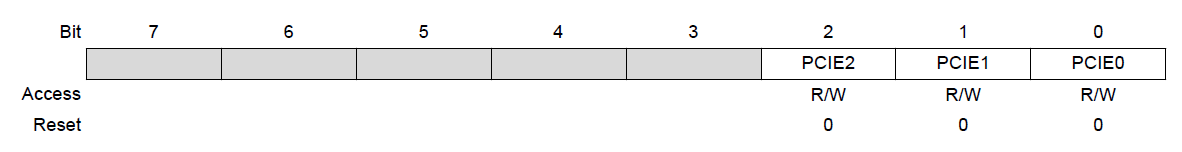
The last three bits of this register are control bits for enabling a PCINT group. When PCIE0 (bit 0) is set, then the PCINT pins 0 to 7 are enabled. These pins are D8 to D13 (excluding crystal pins) in Arduino pin mapping. Similarly, when PCIE1 or PCIE2 bits are set, the PCINT pins 8 to 14 and 16 to 23 are enabled which are equivalent to pins A0 to A5 (excluding reset) and D0 to D7 respectively.
Now when these interrupts are triggered, there will be corresponding flag bits that will be set. These flag bits are found at register PCIFR:
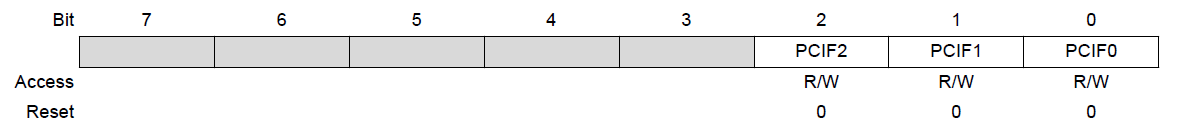
So when PCIE0 is enabled and the interrupt is triggered, PCIF0 bit will be set. The same is true for the rest of the flag bits.
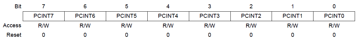
Now what if we only want to enable specific pin(s) within a group? That is done using the PCMSK register. There are three PCMSK registers for each group. Each bit in the PCMSK register corresponds to a PCINT pin:
PCMSK0:
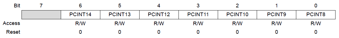
PCMSK1:
PCMSK2:
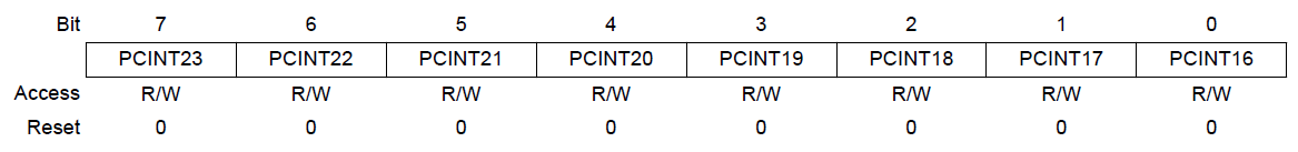
PCMSK0 is used to enable each PCINT pins 0 to 7; PCMSK1 for PCINT pins 8 to 14; and PCMSK2 for PCINT pins 16 to 23.
Now let’s proceed to an example. Let’s say we want to enable pin change interrupt on pin A0.
First, we must set the PCMSK bit for pin A0. This pin is PCINT8 and thus belongs to PCMSK1. So, this line must be included in the sketch:
PCMSK1 = B00000001 //enable PCINT8
Those who have been into AVR programming might be more comfortable writing it this way:
PCMSK1 = (1<<PCINT8) //enable PCINT8
Then, we enable the group interrupt to which A0 belongs to (PCIE1):
PCICR = B00000010 //enable PCIE1 group
Or in another form:
PCICR = (1<<PCIE1) //enable PCIE1 group
The PCIFR register, which houses the pin change interrupt flags need not to be cleared as they are automatically cleared when the ISR is executed. Nevertheless, to clear it manually, you need to set the bit number that corresponds to the pin group. For the A0 pin, that would be bit PCIF1.
How about the ISR function? AVR has its own function ISR() which accepts the interrupt vector for each group. The PCIE0 group has PCINTO_vect, PCIE1 has PCINT1_vect and PCIE2 has PCINT2_vect as their respective vectors. Since we will be only using A0 in this example, this is the only one we need:
ISR(PCINT1_vect){
   //Do the ISR routine here
}
Now here’s the full sketch:
const byte ledPin = 13;
volatile byte state = LOW;

void setup(){
   pinMode(ledPin, OUTPUT);
   pinMode(A0, INPUT_PULLUP);
   PCMSK = B00000001; //enable PCINT8
   PCICR = B00000010; // enable PCIE1 group
}

void loop(){
   digitalWrite(ledPin, state);
}

ISR(PCINT1_vect) {
   state = !state;
}
To use the sketch above, use this diagram:
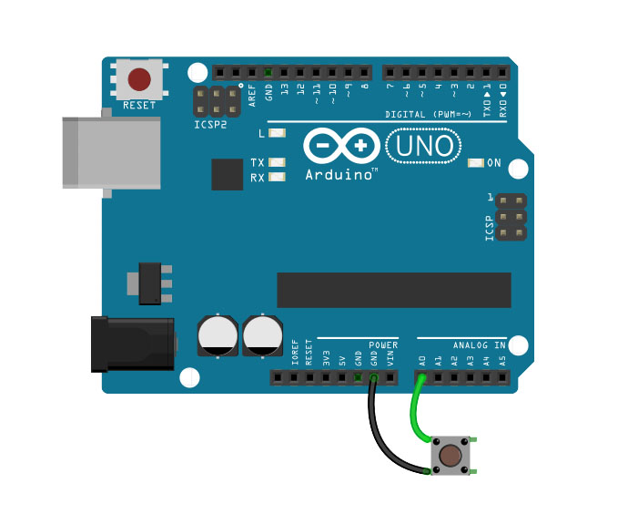
Every time you push the button at A0, the on-board LED should light up. That’s interrupt programming!
Pin Change Interrupt Library
Now if manipulating registers is not your thing, there is a simple pin change interrupt library you can use. Download it here.
Here’s the same sketch as above but implemented using the PinChangeInt library:
#include <PinChangeInt.h>

const byte ledPin = 13;
volatile byte state = LOW;

void setup(){
   pinMode(ledPin, OUTPUT);
   pinMode(A0, INPUT_PULLUP);
   PCintPort::attachInterrupt(A0, isr, CHANGE);
}

void loop(){
   digitalWrite(ledPin, state);
}

void isr() {
   state = !state;
}
No more registers! All you need is attach the interrupt on the pin using:
PCintPort::attachInterrupt(A0, isr, CHANGE);
Also on this function is the name of the isr function and the trigger mode.

