
In this Arduino LCD tutorial, you will learn how to display characters (text and numbers) on a 16 x 2 LCD which is very useful in debugging microcontroller projects as well as providing text-based status for your systems.
Introduction
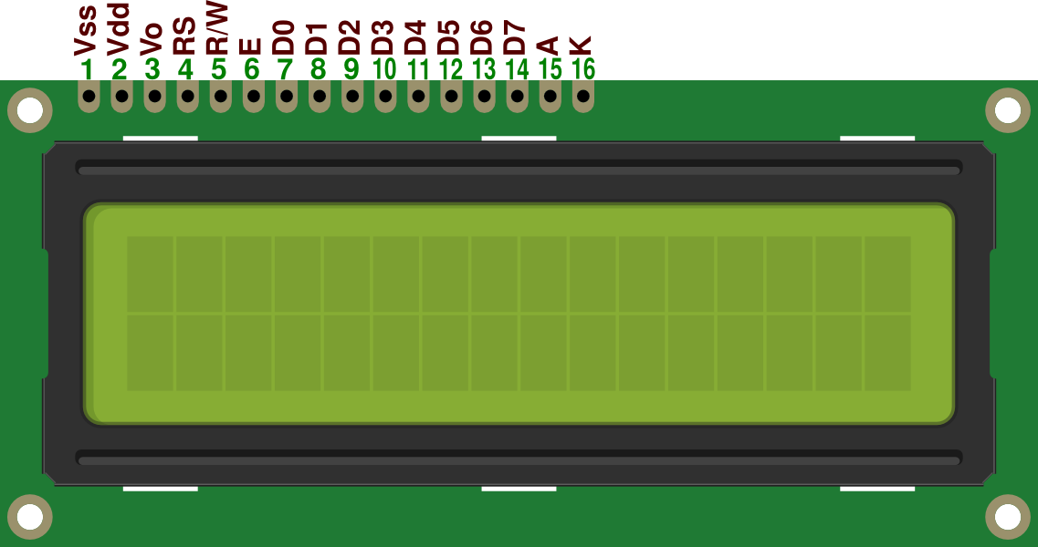
The widely used 16 x 2 character LCD uses the HD44780 controller from Hitachi which has been around since 1987. The LCD's parallel interface makes it faster than I2C and SPI LCD's but the trade off is you need a lot more wires. Here's the LCD's pinout:
- Vss = GND pin.
- Vdd = +3V or +5V pin.
- Vo = use for contrast adjust.
- RS = register select pin.
- R/W = read/write pin.
- E = enable pin.
- D0 - D7 = data pins.
- A = anode pin (+5v) for backlight.
- K = cathode pin (GND) for backlight.
That's a lot of pins to connect to an Arduino. Thankfully, this LCD has a four-bit mode which means you don't have to use all 8 data pins. The R/W pin is almost always connected to ground since R/W = 0 is writing to the LCD and R/W = 1 is reading to the LCD (which doesn't happen very often). So that leaves six Arduino pins to be used with this LCD plus the VDD and A (+3.3V or +5V) and VSS and K(GND) pins. Now let's start coding!
Simple Arduino LCD Code
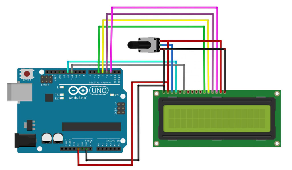
Connect the following circuit:
We’ll be using the example sketch “HelloWorld” from Arduino’s built-in LiquidCrystal library. Open the Arduino IDE, then go to File > Examples > LiquidCrystal > HelloWorld. You should be seeing this code:
// include the library code:
#include <LiquidCrystal.h>

// initialize the library with the numbers of the interface pins
LiquidCrystal lcd(12, 11, 5, 4, 3, 2);

void setup() {
  // set up the LCD's number of columns and rows:
  lcd.begin(16, 2);
  // Print a message to the LCD.
  lcd.print("hello, world!");
}

void loop() {
  // set the cursor to column 0, line 1
  // (note: line 1 is the second row, since counting begins with 0):
  lcd.setCursor(0, 1);
  // print the number of seconds since reset:
  lcd.print(millis() / 1000);
}
Note that I purposely removed the comments above this code. Those comments are important for beginners as it includes the connection between the LCD and the Arduino. The schematic shown above follows that same connection.
Upload the code to your Arduino and you should see the display “hello, world!” on the first line and a number counting every second in the second line.
Now let’s dissect the code.
The most important part is the inclusion of the LiquidCrystal library.
#include <LiquidCrystal.h>
Without this line, we can’t use the functions associated with LCD control.
The line:
LiquidCystal lcd(12, 11, 5, 4, 3, 2);
initializes the lcd object followed by the Arduino pin numbers assigned to RS, E, D4 to D7 respectively. This means you can actually assign which pins you can use with the LCD pins. You don’t also need to set the pinModes of these pins as they are automatically configured.
Next, you need to specify the screen size of the LCD. This is what the line:
lcd.begin(16, 2);
is for. 16 is the number of columns and 2 is the number of rows.
To write a message on the LCD, you use the command:
lcd.write(“hello, world!”)
To move the cursor, you can use the command:
lcd.setCursor(x,y);
Where x is the horizontal position and y is the vertical position. For a 16 x 2 LCD, x is from 0 to 15 while y is 0 to 1. Other useful commands, not shown in the example are:
lcd.Display()
lcd.noDisplay()
lcd.cursor()
lcd.noCursor()
The lcd.Display() and lcd.noDisplay() turns on and off the LCD respectively. Similarly, the lcd.cursor() and lcd.noCursor() turns on and off the cursor.
Here’s the list of all Arduino LCD functions.
I2C LCD Interface
If you're having problems with the number of pins used for the LCD, then this solution might be for you: use I2C! There exists a module that accepts I2C data and converts them to parallel data that is understandable by the 16x2 LCD. Here is that module:

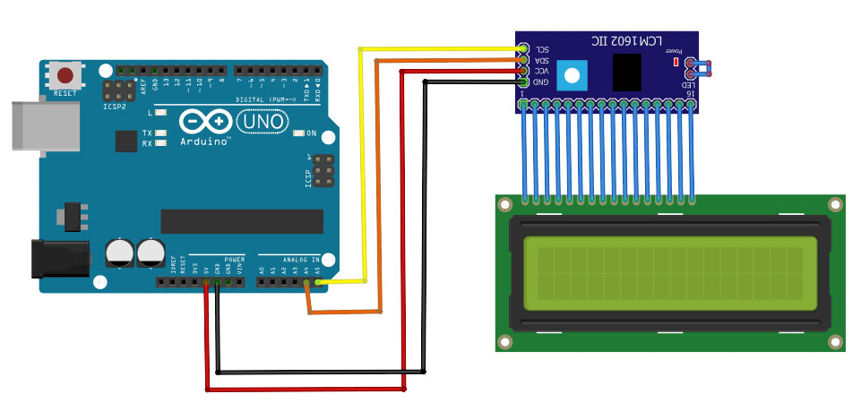
Here is the module installed:
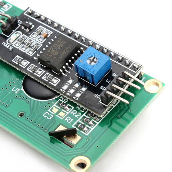
With this module, you will only need four pins! Here's how you should connect it to your Arduino:
To use this module, we first need to know its I2C address. Here's a sketch that scans I2C devices that is connected to an Arduino:
#include <Wire.h>

void setup()
{
  Wire.begin();
  Serial.begin(9600);
  while (!Serial);             //  wait for serial monitor
  Serial.println("\nI2C Scanner");
}

void loop()
{
  byte error, address;
  int nDevices;

  Serial.println("Scanning...");

  nDevices = 0;
  for(address = 1; address < 127; address++ )
  {
    // The i2c_scanner uses the return value of
    // the Write.endTransmisstion to see if
    // a device did acknowledge to the address.
    Wire.beginTransmission(address);
    error = Wire.endTransmission();

    if (error == 0)
    {
      Serial.print("I2C device found at address 0x");
      if (address<16)
        Serial.print("0");
      Serial.print(address,HEX);
      Serial.println("  !");

      nDevices++;
    }
    else if (error==4)
    {
      Serial.print("Unknown error at address 0x");
      if (address<16)
        Serial.print("0");
      Serial.println(address,HEX);
    }
  }
  if (nDevices == 0)
    Serial.println("No I2C devices found\n");
  else
    Serial.println("done\n");

  delay(5000);           // wait 5 seconds for next scan
}
Upload this sketch and the serial monitor in the IDE. You will then see the I2C address of the module.
After you have acquired the I2C address of the module, display something on your screen using the sketch below. You will need the I2C LiquidCrystal library.
#include <Wire.h>
#include <LiquidCrystal_I2C.h>

// Set the LCD address to 0x27 for a 16 chars and 2 line display
LiquidCrystal_I2C lcd(0x27, 16, 2);

void setup()
{
	// initialize the LCD
	lcd.begin();

	// Turn on the blacklight and print a message.
	lcd.backlight();
	lcd.print("Hello, world!");
}

void loop()
{
	// Do nothing here...
}
See my separate post on Arduino I2C LCD for more!
If this tutorial helped you in some way, do send me a message via the contact page. Have fun building!

