
This Arduino LiPo battery monitor and charger feature the TP4056 breakout board. The voltage level of the battery is displayed on a Nokia 3310/5110 LCD with the Arduino Nano as the microcontroller.
Materials
- Arduino Nano
- TP4056 Breakout Board
- Nokia 3310/5100 LCD
- 3.7 V LiPo Battery
- Connecting Wires and Breadboard
Introduction
The TP4056 breakout board input ports are microUSB and +, - pads. The output ports are and OUT+, OUT-, B+, B- pads.
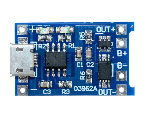
Naturally, the input voltage should be 5V DC on both the USB port and the +, - terminals. The battery is connected to the B+ and B- terminals. The current voltage of the battery is readable through the OUT+ and OUT- pads.
Once the input voltage and battery is connected, one of the on-board LED lights up. The red LED turns on when the battery is still charging. The green LED turns on when the charging reaches the full-charge voltage of 4.2 V. Here lies the limitation of the LED indication because some LiPo batteries are rated to 3.7 V. Obviously, the LED would not turn green for these batteries because it won’t reach 4.2 V.
So I had the idea of creating a battery monitor for my 3.7 V LiPo battery. The voltage of the battery will be fed to any of the analog pins of the arduino and then displayed on the LCD.
Wiring Diagram
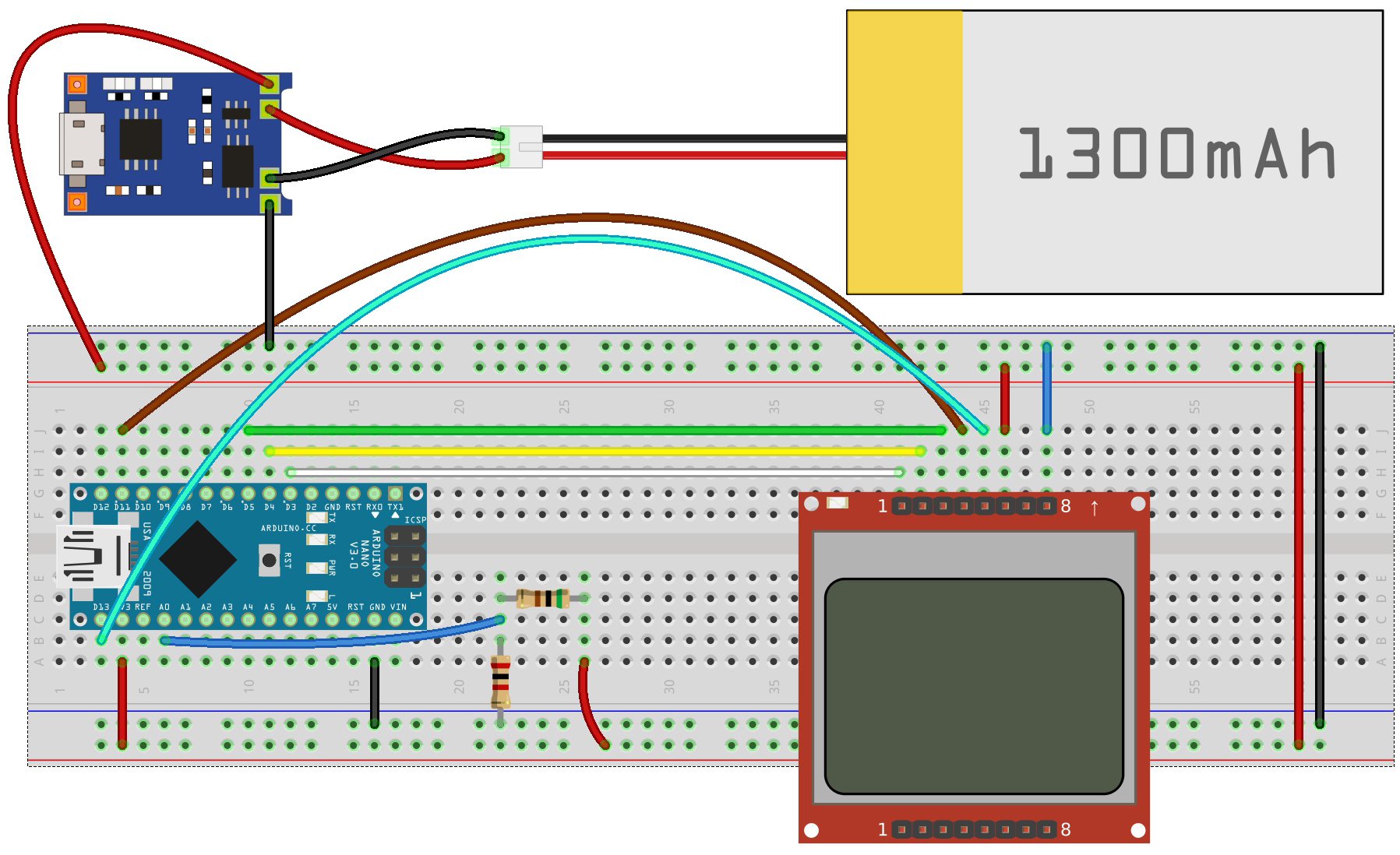
The circuit gets its power from the battery itself. To avoid ADC reading errors due to the possible drift in battery voltage, I used the internal reference voltage of the arduino nano/atmega328p. This 1.1V reference voltage doesn’t drift with supply voltage so it’s a good thing. However, this would also mean that the maximum voltage that can be feed to A0 is 1.1V. So, I had to include a voltage divider circuit to reduce the input voltage at A0. The expected maximum input voltage is equal to the full-charge voltage of the battery, 3.7 V. I decided to use the following resistor values:
The maximum input voltage now would be
This is now well within the 1.1 V max limit!
Arduino Sketch
The required library for the sketch is Adafruit’s GFX and PCD8544 libraries. See my Arduino Nokia 3310 LCD tutorial for more information.
/*
 Arduino LiPo Battery Monitor
 By Roland
 from: https://www.teachmemicro.com/arduino-lipo-battery-monitor
*/

#include <SPI.h>
#include <Adafruit_GFX.h>
#include <Adafruit_PCD8544.h>

Adafruit_PCD8544 display = Adafruit_PCD8544(5, 4, 3);

float ARef = 1.1;

void setup() {
  // put your setup code here, to run once:
   analogReference(INTERNAL);
   display.begin();
   display.setContrast(40);
   display.setTextSize(2);
   display.setTextColor(BLACK);
}

void loop() {
  // put your main code here, to run repeatedly:
  float raw = analogRead(A0);
  float x = raw/1023;
  float voltage = x*ARef*4;
  display.clearDisplay();
  display.print(" ");
  display.print(voltage);
  display.println(" V");
  if(voltage > 0 && voltage < 1){
    //one bar
    display.fillRect(15,30,10,15,BLACK);
  }else if(voltage > 1 && voltage < 2.775){
    //two bar
    display.fillRect(15,30,10,15,BLACK);
    display.fillRect(25,30,5,15,WHITE);
    display.fillRect(30,30,10,15,BLACK);
  }else if(voltage > 2.775 && voltage < 3.7){
    //three bar
    display.fillRect(15,30,10,15,BLACK);
    display.fillRect(25,30,5,15,WHITE);
    display.fillRect(30,30,10,15,BLACK);
    display.fillRect(40,30,5,15,WHITE);
    display.fillRect(45,30,10,15,BLACK);
  }else{
    display.fillRect(15,30,10,15,BLACK);
    display.fillRect(25,30,5,15,WHITE);
    display.fillRect(30,30,10,15,BLACK);
    display.fillRect(40,30,5,15,WHITE);
    display.fillRect(45,30,10,15,BLACK);
    display.fillRect(55,30,5,15,WHITE);
    display.fillRect(60,30,10,15,BLACK);
  }
  display.display();
  delay(1000);
}
Noticed this line?
float ARef = 1.1;This is the reference voltage I was talking about. This is used in calculating the real voltage value later one.
To use the internal reference, this line is required:
analogReference(INTERNAL);On the loop(), I just needed to read the voltage on the A0 pin:
float raw = analogRead(A0);I then converted this value to voltage with a couple of lines:
float x = raw/1023;
float voltage = x*ARef*5;
My discussion on arduino sensor interfacing showed how to calculate the voltage from the raw value. Basically, the minimum voltage the arduino can read is Aref/1023 = 1.075 mV. So let’s say the input voltage from the battery is 1.7 V, which is brought down to 0.34 V by the voltage divider, the ADC value would be:
ADC = 0.34 / 1.1 * 1023 = 316.2
To convert this value to the actual voltage, I just reverse the formula above: divide by 1023 and then multiply by the reference voltage (1.1 V) and the voltage divider factor (1/0.2 = 5):
actual voltage = ADC / 1023 * 1.1 * 5 = 1.7 V
I also added some bars below the voltage value as seen:
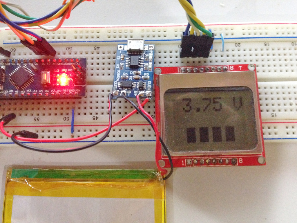
This uses the fillRectangle() function of the graphics library. I draw one rectangle for every ¼ value of the full-charge voltage.
if(voltage > 0 && voltage < 1){
 //one bar
 display.fillRect(15,30,10,15,BLACK);
 }else if(voltage > 1 && voltage < 2.775){
 //two bar
 display.fillRect(15,30,10,15,BLACK);
 display.fillRect(25,30,5,15,WHITE);
 display.fillRect(30,30,10,15,BLACK);
 }else if(voltage > 2.775 && voltage < 3.7){
 //three bar
 display.fillRect(15,30,10,15,BLACK);
 display.fillRect(25,30,5,15,WHITE);
 display.fillRect(30,30,10,15,BLACK);
 display.fillRect(40,30,5,15,WHITE);
 display.fillRect(45,30,10,15,BLACK);
 }else{
 display.fillRect(15,30,10,15,BLACK);
 display.fillRect(25,30,5,15,WHITE);
 display.fillRect(30,30,10,15,BLACK);
 display.fillRect(40,30,5,15,WHITE);
 display.fillRect(45,30,10,15,BLACK);
 display.fillRect(55,30,5,15,WHITE);
 display.fillRect(60,30,10,15,BLACK);
 }
It looks bad but I promise to create better graphics on future updates 🙂
Did you find this project useful? Please drop a comment below!

