
In control systems, a controller corrects the output of a particular system to a target in the presence of errors and disturbances. The most popular type of controller is PID which is an acronym for Proportional, Integral, and Derivative. In this Arduino PID control tutorial, I will show you how you can employ such a controller in your project.
What is PID?
As mentioned, PID is short for proportional, integral, and derivative. The name comes from the methods of how such controllers deal with disturbances in the system. However, such a controller is only in feedback systems. I suggest reading material specifically written for such a topic, but I’ll do my best to explain it here as simply as I can.
A feedback system is wherein part of the output is “fed back” to the input. For example, you could have a project that controls the fire in the furnace. Below is a simple illustration:
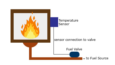
You want to maintain the temperature in the furnace to a certain set point. A temperature sensor in the furnace determines the temperature at any time. This sensor, in this case, provides the feedback as a reference on the required temperature increase or decrease. The difference between the feedback sensor value and a temperature set point is the error.
Proportional Control
Proportional control refers to an adjustment that is proportional to how much the error is. Let’s say the controller in our example is an electronic valve for controlling the fuel to the furnace. If the error is small, the valve will release a small amount of fuel so that the set point and the feedback match. If the error is large, the valve must release more fuel.
Integral Control
Proportional control produces offset in its correction due to disturbances. The Integral controller can remove this offset and bring back the error to zero. Such a controller produces an adjustment that is based on the accumulated error over time. Without integral control, the system can’t deal with trends on errors.
Using our previous example, an offset may be present when the fuel valve doesn’t return to its original position when it increases and then decreases its fuel output. The integral controller will detect this and will turn the fuel valve to its original position.
Derivative Control
Finally, Derivative control deals with the rate of change of the error. If integral control looks at the history of the error, derivative control predicts the error. Basically, the amount of correction will be based on how fast the error is changing. This type of controller works best with dynamic errors which both proportional and integral controllers can’t deal with.
Let’s say the temperature in the furnace goes from 130 °C to 140 °C against a 120 °C set point in 2 seconds. The proportional and integral controllers will respond to the magnitude of the error, but they will have a hard time catching up to how fast the error occurred.. The derivative controller can deal with such because it has been looking at the rate of change of the error from the beginning.
A feedback system with a PID controller:
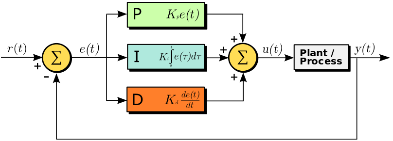
Here the input variable or set point is r(t), the output variable is y(t), the controlled variable is u(t) and the error is e(t). Continuing with our furnace example, r(t) would be the desired temperature and y(t) is the actual temperature; e(t) is the difference between the desired temperature and actual temperature; u(t) is the sum of the corrections from the P, I and D controllers which are fed to the plant which is the fuel valve.
Note that a PID controller is not usable out of the box. Tuning must be done to ensure that the desired performance is achieved. This is done by carefully changing K constants as shown on the diagram above. These constants must be determined beforehand and changed according to the actual response of the system until the optimum values are achieved.
Implementing PID in Code
To implement a PID controller in a code or an Arduino sketch, five parameters must be known: proportional, integral, and derivative constants, input value, and set point value.
PID computation must be inside a looping function. The first part of the function should be determining the time elapsed. In Arduino, the function millis() returns the time in milliseconds since the start of the program. Hence, the elapsed time is just:
currentTime = millis();
elapsedTime = currentTime - previousTime;
Next, the error must be determined:
error = setPoint - input;
Recall that the integral of the error is the cumulative error over time. To calculate an integral using Arduino, we simply do:
cumError += error * elapsedTime;
The derivative of the error is the rate of change of the error:
rateError = (error - lastError)/elapsedTime;
Finally, the computed output is:
output = Kp * error + Ki * cumError + Kd * rateError;
Here, the Kp, Ki, and Kd are the predetermined constants.
Finally, the variables must be noted for the next iteration:
lastError = error;
previousTime = currentTime;
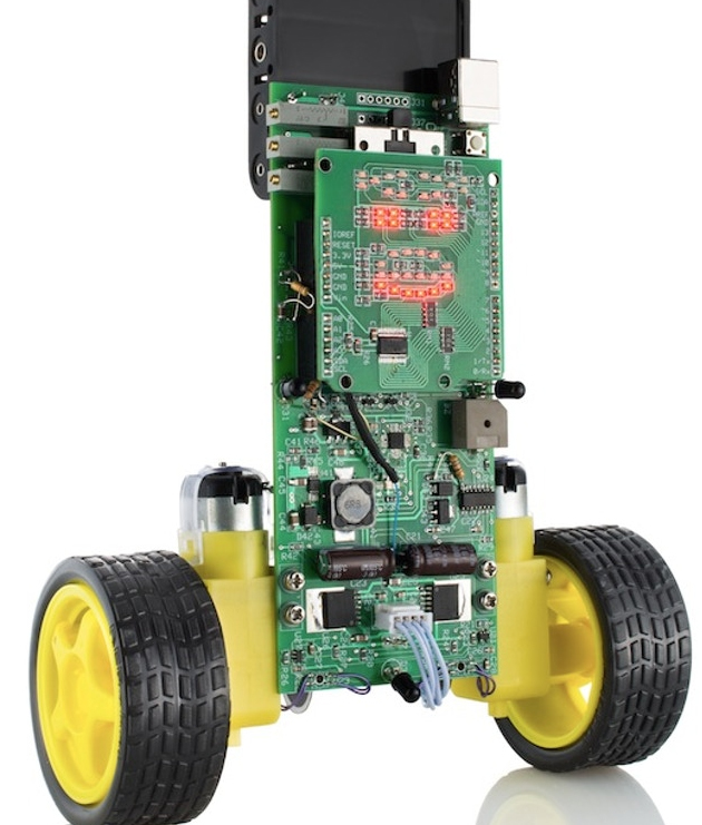
Let’s try a more concrete example. Imagine a wheel attached to a motor. We want the wheel to remain in the position shown:
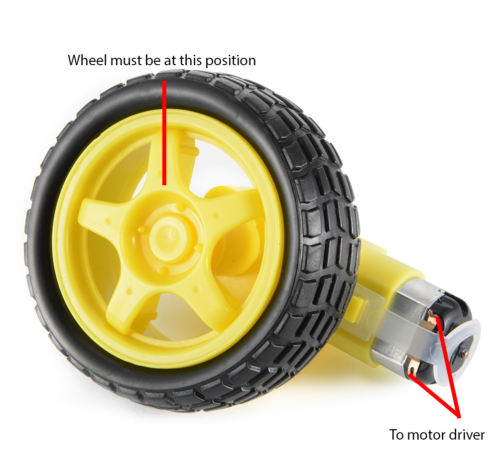
A rotary encoder on the wheel gives the angle in degrees of the current wheel position. At our target wheel position, the angle is zero.
What we want is for the motor to turn whenever the wheel is out of position. Furthermore, the motor is controlled through pulse width modulation. The wider the pulse, the farther the motor rotates.
Next, let us implement this simple control system using an Arduino.
PID Controller - Arduino Code:
//PID constants
double kp = 2
double ki = 5
double kd = 1

unsigned long currentTime, previousTime;
double elapsedTime;
double error;
double lastError;
double input, output, setPoint;
double cumError, rateError;

void setup(){
        setPoint = 0;                          //set point at zero degrees
}

void loop(){
        input = analogRead(A0);                //read from rotary encoder connected to A0
        output = computePID(input);
        delay(100);
        analogWrite(3, output);                //control the motor based on PID value

}

double computePID(double inp){
        currentTime = millis();                //get current time
        elapsedTime = (double)(currentTime - previousTime);        //compute time elapsed from previous computation

        error = Setpoint - inp;                                // determine error
        cumError += error * elapsedTime;                // compute integral
        rateError = (error - lastError)/elapsedTime;   // compute derivative

        double out = kp*error + ki*cumError + kd*rateError;                //PID output

        lastError = error;                                //remember current error
        previousTime = currentTime;                        //remember current time

        return out;                                        //have function return the PID output
}
In the loop function, the rotary encoder determines the current position of the wheel and its output value becomes a parameter for the computePID() function. This function returns a value for controlling the motor using PWM.
PID Arduino Code Library
We can further simplify using PID in Arduino projects with the help of Brett Beauregard’s PID library. The library only requires you to specify kd, ki, kp, and setpoint values and you’re good to go!
Here is the PID_Basic.ino sketch that comes with the library. This sketch provides the same output as the sketch above but better:
#include <PID_v1.h>

#define PIN_INPUT 0
#define PIN_OUTPUT 3

//Define Variables we'll be connecting to
double Setpoint, Input, Output;

//Specify the links and initial tuning parameters
double Kp=2, Ki=5, Kd=1;
PID myPID(&Input, &Output, &Setpoint, Kp, Ki, Kd, DIRECT);

void setup()
{
 //initialize the variables we're linked to
 Input = analogRead(PIN_INPUT);
 Setpoint = 100;

 //turn the PID on
 myPID.SetMode(AUTOMATIC);
}

void loop()
{
 Input = analogRead(PIN_INPUT);
 myPID.Compute();
 analogWrite(PIN_OUTPUT, Output);
}
Here, you can create a PID class and have the input, output, setpoint, and k constants as parameters. To compute PID, simply call the Compute() function. It also contains a SetMode() function which turns on (AUTOMATIC) or turns off (MANUAL) the PID. The complete list of functions used by the library is found here.
I say that the sketch above is better than my code because it deals with PID limitations which is beyond the scope of this article.
Closing
Hopefully, you have a slight grasp of how to implement PID control in this article. It is a powerful controller that will reduce manual correction for your systems. If you have any questions about implementing Arduino PID, kindly drop a comment below!

