
If you've coded PICs before Arduinos one of the things you might have noticed is the lack of function on the latter to manipulate multiple pins at once. Manipulating all the Arduino pins at once is needed, for example, when using a seven-segment display or creating strobe lights. Is there a way to read/write multiple pins at once in Arduino?
The Arduino Pins
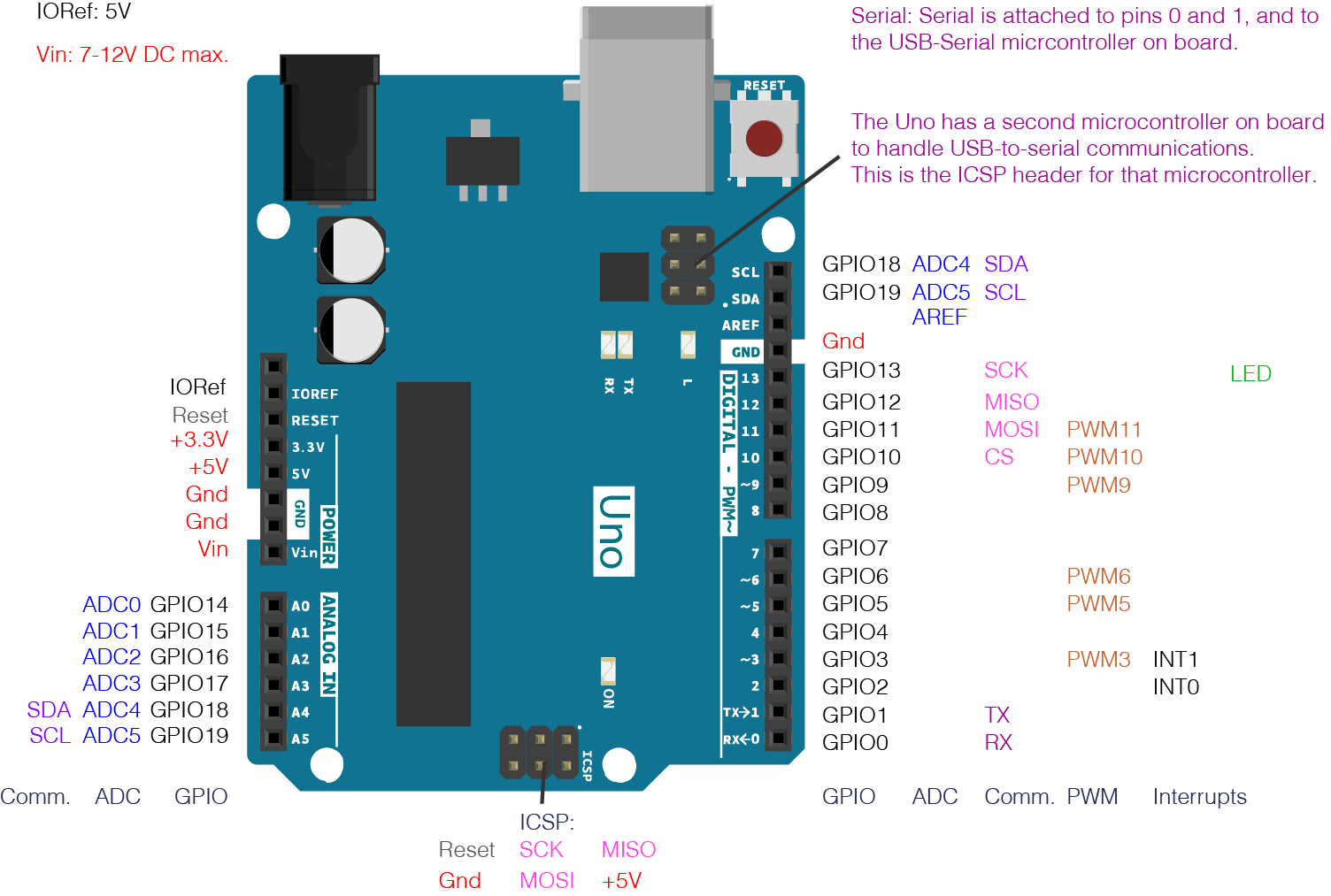
The Arduino, which uses the ATMega328p, is actually the same as a PIC16F877A when it comes to pin manipulation. You only need to specify the name of registers that control the physical ports (or pins). Take a look at the pin mapping of the ATMega328 with the corresponding Arduino pins:
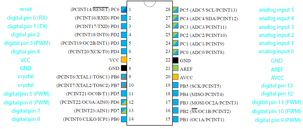
Here you will see that the pins are grouped as power pins, PORTB, PORTC and PORTD.
Each PORT has a corresponding DDR (data direction register) that specifies whether a pin on that port is output or input. A "1" on the DDR pin corresponds to an output on the PORT pin. A "0" on the DDR pin corresponds to an input on the PORT pin.
For example, you want to set digital Arduino pins 2, 3, 4, 5 and 6 as output and digital pins 0, 1 and 7 as inputs. Their ATMega328p pin names are PD2, PD3, PD4, PD5 and PD6; PD0, PD1 and PD7 respectively. Here's how to set them all simultaneously:
DDRD = B01111100;
Now let's say you want to blink Arduino pins 2, 3, 4, 5, and 6 simultaneously with 1 second interval, you could write this:
PORTD = B011111100;
delay(1000);
PORTD = B0000000;
delay(1000);
The original way of coding the same thing as above would be like this:
int i;
void setup(){
 for(i = 2;i<6;i++){
   pinMode(i, OUTPUT);
 }
}

void loop(){
 for(i = 2;i<6;i++){
   digitalWrite(i, HIGH);
 }
 delay(1000);
 for(i = 2;i<6;i++){
   digitalWrite(i, LOW);
 }
}
Using registers, it would be like this:
void setup(){
 DDRD =  B01111100;
}

void loop(){
 PORTD = B011111100;
 delay(1000);
 PORTD = B0000000;
 delay(1000);
}
Arduino Pins Example
Now you might not appreciate what we've done here because the difference is subtle. Let's try another example.
Suppose you want to use a common cathode seven-segment display connected to the Arduino pins without using a driver of some sort. Digital pins 2 to 8 is connected to seven-segment pins a to f.
To display the digit 7, for example, you need the seven segment pins a, b, c to be high and the rest to be low.
This would be common way to do that:
void setup(){
 pinMode(2, OUTPUT);
 pinMode(3, OUTPUT);
 pinMode(4, OUTPUT);
 pinMode(5, OUTPUT);
 pinMode(6, OUTPUT);
 pinMode(7, OUTPUT);
 pinMode(8, OUTPUT);
}

void loop(){
 digitalWrite(2, HIGH)
 digitalWrite(3, HIGH)
 digitalWrite(4, HIGH)
 digitalWrite(5, LOW)
 digitalWrite(6, LOW)
 digitalWrite(7, LOW)
 digitalWrite(8, LOW)
}
What if you want to display 7 and 8 in sequence? You could do this:
void setup(){
 pinMode(2, OUTPUT);
 pinMode(3, OUTPUT);
 pinMode(4, OUTPUT);
 pinMode(5, OUTPUT);
 pinMode(6, OUTPUT);
 pinMode(7, OUTPUT);
 pinMode(8, OUTPUT);
}

void loop(){
 digitalWrite(2, HIGH)
 digitalWrite(3, HIGH)
 digitalWrite(4, HIGH)
 digitalWrite(5, LOW)
 digitalWrite(6, LOW)
 digitalWrite(7, LOW)
 digitalWrite(8, LOW)
 delay(1000);
 digitalWrite(2, HIGH)
 digitalWrite(3, HIGH)
 digitalWrite(4, HIGH)
 digitalWrite(5, HIGH)
 digitalWrite(6, HIGH)
 digitalWrite(7, HIGH)
 digitalWrite(8, HIGH)
 delay(1000);
}
What if you want to display all the digits sequentially from 1 to 8? The code would be too long!
The easier way is to use registers. To display the digit 7, you can simply do:
void setup(){
 DDRD = B11111100;  //Digital pins 2 to 7 as output
 DDRB = B00000001; //Digital pin 8 as output
}

void loop(){
 PORTD = B00011100;
 PORTB = B00000001;
 delay(1000);
}
To display digits 7 and 8 in sequence:
void setup(){
 DDRD = B11111100;  //Digital pins 2 to 7 as output
 DDRB = B00000001; //Digital pin 8 as output
}

void loop(){
 PORTD = B00011100;
 PORTB = B00000000;
 delay(1000);
 PORTD = B11111100;
 PORTB = B00000001;
 delay(1000);
}
Displaying All Digits
To display all digits, we can use an array that stores all the bit combination for the digits. Here they are for reference:
| Digit gfedcba | a | b | c | d | e | f | g | |
| 0 0×3F | on | on | on | on | on | on | off | |
| 1 0×06 | off | on | on | off | off | off | off | |
| 2 0×5B | on | on | off | on | on | off | on | |
| 3 0×4F | on | on | on | on | off | off | on | |
| 4 0×66 | off | on | on | off | off | on | on | |
| 5 0×6D | on | off | on | on | off | on | on | |
| 6 0×7D | on | off | on | on | on | on | on | |
| 7 0×07 | on | on | on | off | off | off | off | |
| 8 0×7F | on | on | on | on | on | on | on | |
| 9 0×6F | on | on | on | on | off | on | on |
We need to define an array that contains the binary combination for the different digits. They should be in sequence (0 to 9) for easier access:
char digit[10] = {0x3F, 0x06, 0x5B, 0x4F, 0x66, 0x6D, 0x7D, 0x07, 0x7F, 0x6F};
For example, displaying the digit 7 would have to be like this:
char digit[10] = {0x3F, 0x06, 0x5B, 0x4F, 0x66, 0x6D, 0x7D, 0x07, 0x7F, 0x6F};
void setup() {
  DDRD = B11111100;
  DDRB = B00000001;
}
void loop() {
  PORTD = digit[7] << 2; PORTB = (B01000000 & digits[7]) >> 6;
}
PORTD is equal to the value of digit[7] with bits shifted two positions to the left. This is because we used PORTD.2 to PORTD.7 instead of PORTD.0 to PORTD.7.
The last segment (f) is connected to PB0. This would be bit 6 of digit[7]. To get only bit 6 of digit[7], a logical AND of B01000000 and digit[7] is done. The result of the logical AND operation is then shifted six positions (to LSB or PORTB.0) whose result is then stored to PORTB.
The Final Code
Now to display all digits in sequence from 0 to 9, your code would be like this:
char digit[10] = {0x3F, 0x06, 0x5B, 0x4F, 0x66, 0x6D, 0x7D, 0x07, 0x7F, 0x6F};

void setup() {
 DDRD = B11111100;
 DDRB = B00000001;
}

void loop() {
 for(int i = 0;i<10;i++){
 PORTD = digit[i] << 2; PORTB = (B01000000 & digit[i]) >> 6;
 delay(1000);
 }
}
If you find this post useful, kindly comment below. Happy coding!

