

A RGB LED is a special light-emitting diode that can produce 16 million possible colors, all by combining the colors red, green, and blue in varying intensities. This tutorial will show you how to use a RGB LED with Arduino.
Introduction to RGB LEDs
RGB LEDs typically have four pins as shown:
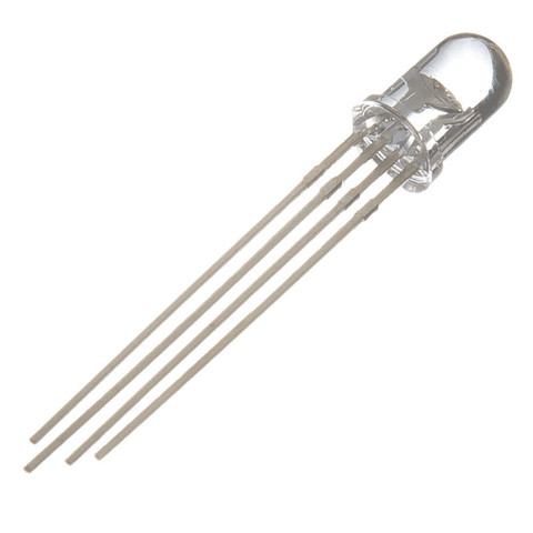
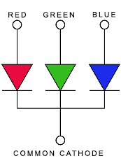
Such LED is the same as a red, green, and blue LED connected like this, hence the four pins:
Which pin is red, green, or blue? The length of the pins tells us this:
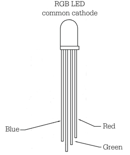
The shortest pin is always the red LED. The blue LED is the next shortest and then followed by the green LED. Just like the normal LED, the longest pin is the common cathode pin.
The diagrams above are for a type of RGB LED where the cathode is common. For a common anode RGB LED, the diagram is reversed:
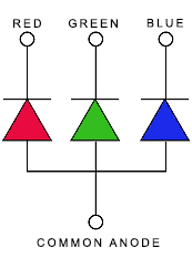
A common anode RGB LED looks the same as a common cathode type but the longest pin is now the common anode pin.
Connecting RGB LED to Arduino
Obviously, connecting a common cathode RGB LED to Arduino is different from connecting a common anode RGB LED.
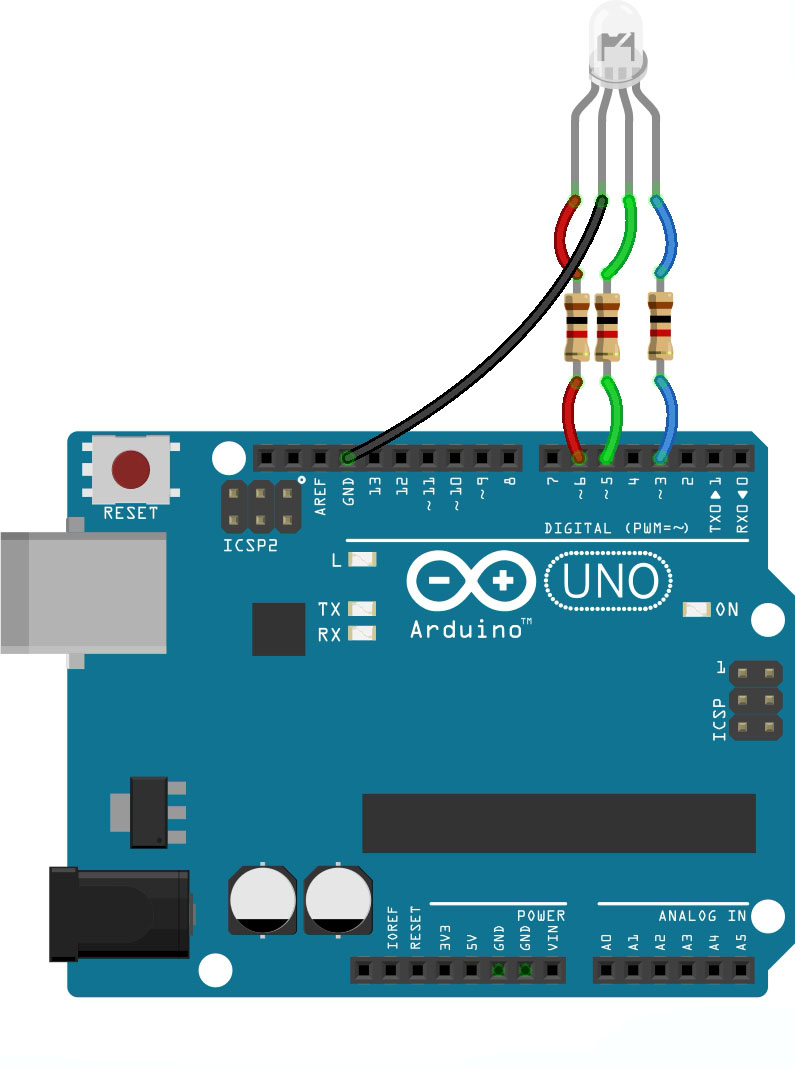
Here is a Fritzing diagram on how to connect a common cathode RGB LED:
On the other hand, this is how you would connect a common anode RGB LED:
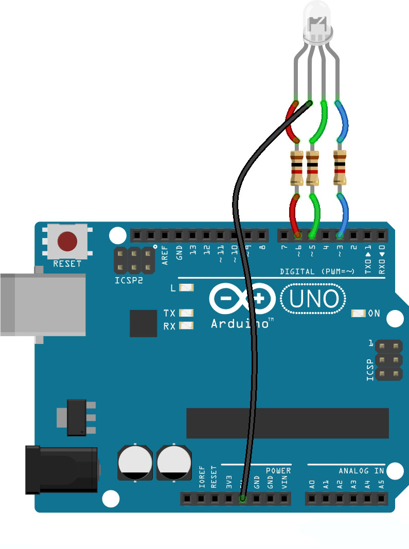
See the difference? For a common cathode LED, the common pin is connected to GND. For a common anode LED, the common pin is connected to 5V.
The resistors in the diagrams are there to limit the current to the LED. Possible values are 220 ohms to 1k ohms. You might think that only one resistor is needed and should be connected to the common pin. That would result in an uneven current distribution on the LED when you want to produce a color besides red, green, and blue.
Also, noticed that the R, G, and B pins are connected to the PWM pins. That’s because to produce different colors, we need to combine red, green, and blue lights at different intensities. The intensity of the LED can only be varied using analogWrite() and this function is only usable for PWM pins.
Beginner Sketch
Here is a sketch that toggles between red, green, and blue colors:
int r = 6;
int g = 5;
int b = 3;

void setup() {
 pinMode(r,OUTPUT);
 pinMode(g,OUTPUT);
 pinMode(b,OUTPUT);
}


void loop() {
  analogWrite(r,255);
  analogWrite(g,0);
  analogWrite(b,0);
  delay(1000);
  analogWrite(r,0);
  analogWrite(g,255);
  analogWrite(b,0);
  delay(1000);
  analogWrite(r,0);
  analogWrite(g,0);
  analogWrite(b,255);
  delay(1000);
}
[the_ad id="3059"]
Note that this sketch is for a common cathode RGB LED and follows the fritzing diagram for such LED above. Here, the color red is produced when I run these commands:
analogWrite(r,255);
analogWrite(g,0);
analogWrite(b,0);
The color green is produced when I do this:
analogWrite(r,0);
analogWrite(g,255);
analogWrite(b,0);
And finally, the color blue is produced through this:
analogWrite(r,0);
analogWrite(g,0);
analogWrite(b,255);
So toggling between the three colors is just placing these commands inside the loop() with delay in between.
Producing Any Color
Now what if you want another color aside from red, green, or blue? Remember that you have 16 million colors to choose from!
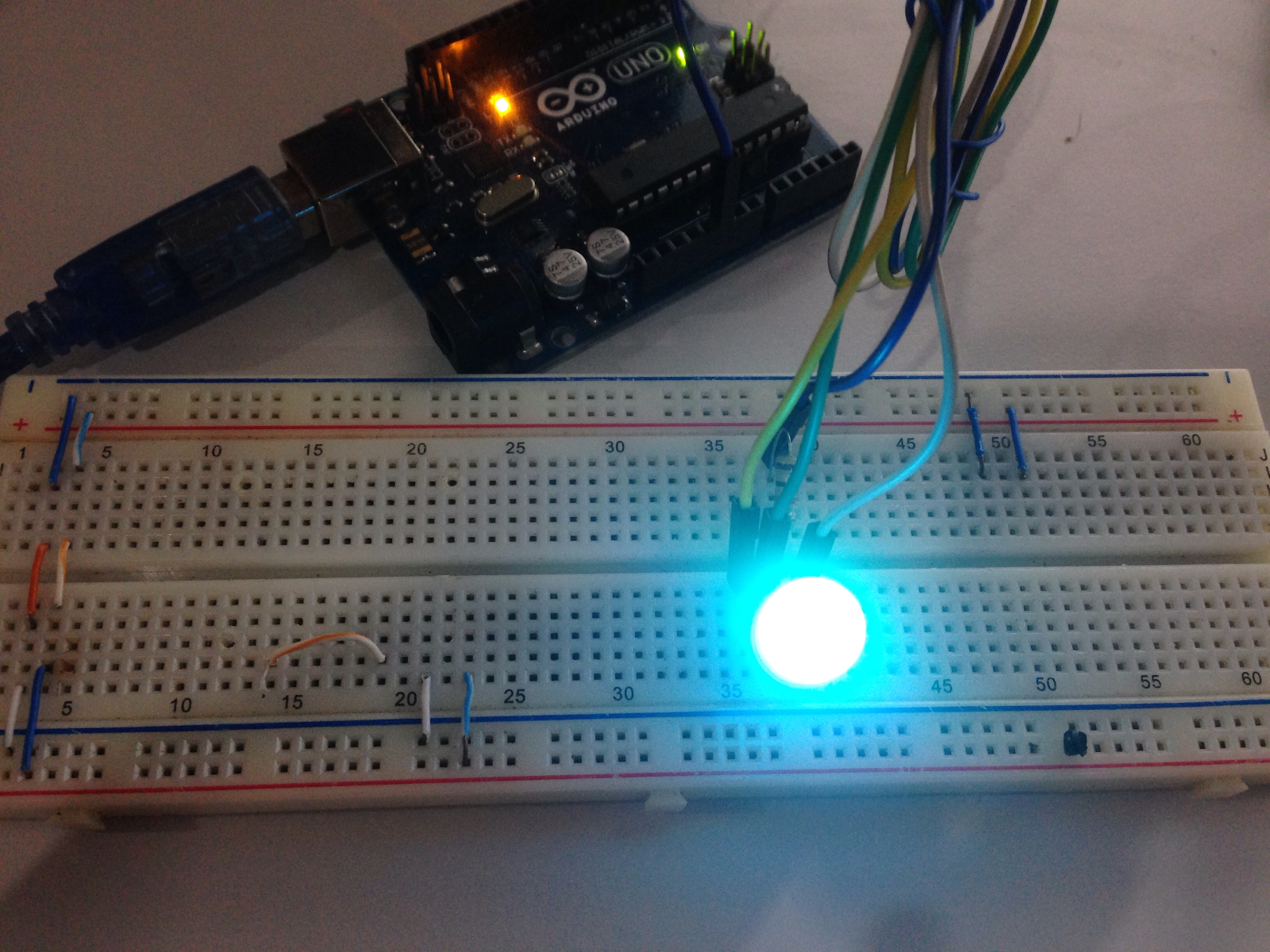
I found this website that gives the RGB values for different colors. For example, the color turquoise is RGB (6%, 87%, 69%) according to that website. This is converted to analogWrite() by just dividing those numbers by 100 and multiplying by 255. So turquoise is produced when I write this out:
analogWrite(r, 15)
analogWrite(g, 222)
analogWrite(b, 176)
And yes it is turquoise:
Arduino RGB LED Library
Bret Stetham created a great library that makes Arduino RGB programming easier. Instead of writing three analogWrites(), the library allows you to write colors in one line of code:
rgbLed.writeRGB(0,255,0);
But what I liked most about the library is the color wheel function. Here’s an example:
[the_ad id="3059"]
#include <RGBLED.h>

// Declare an RGBLED instanced named rgbLed
// Red, Green and Blue LED legs are connected to PWM pins 11,9 & 6 respectively
// In this example, we have a COMMON_ANODE LED, use COMMON_CATHODE otherwise
RGBLED rgbLed(6,5,3,COMMON_CATHODE);

//How long to show each color in the example code (in milliseconds);
int delayMs = 1000;

void setup() {
}

void loop() {
  //Show the color wheel
  //Use a 25ms delay between each color in the wheel
  rgbLed.writeColorWheel(25);
}
Yeah, producing the color wheel looks very easy here but it’s actually quite complicated. Bret had to change the RGB values to HSV which is short for hue, saturation, and value. It turns out, it is easier to produce colors if HSV is given rather than percentages in RGB.

