
To kick off 2019, I would like to create a series of Arduino Robot projects that anyone can learn how to build. The first part of the series is the popular obstacle-avoiding Arduino robot.
An obstacle-avoiding robot is a simple wheeled machine that avoids any obstacle in front of it. The obstacle can be detected using ultrasonic or infrared signals; these signals can be reflected back to their source by solid objects. For this project, I will be using an infrared sensor to detect the obstacle.
Materials
I chose to buy my own robot body primarily to reduce building time and also because it's very cheap. The circular robot body comes with two geared DC motors with wheels and an AA battery holder. There are also holes on the chassis for mounting the Arduino board and other needed modules.
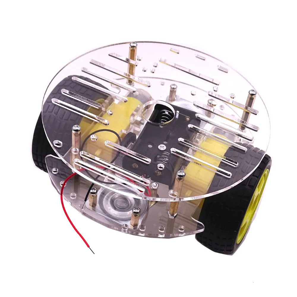
I decided to use three 18650 Li-Po batteries as power source which gives around 11 volts. The L298N module isn't like the one I featured in my tutorial but it's basically the same except for a power button which makes it better (because I don't have to include a switch on this robot).
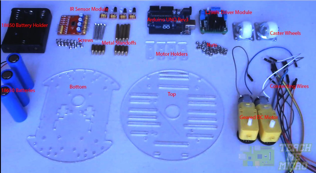
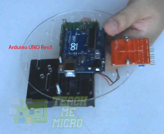
- Arduino UNO Rev3 or similar
- Circular Robot Kit which contains:
- 2 x Geared DC Motors
- Top and Bottom Chassis
- 2 x Caster Wheels
- Metal Standoffs
- Screws and Nuts
- Infrared Avoidance Sensor Module
- L298N Motor Driver Module
- 3 x 18650 Batteries with Holder
- Connecting Wires
Of course, any robot body can be used with this project, as long as we have the same type of obstacle sensor (IR), motor driver (L298N) and microcontroller (Arduino).
Construction
As mentioned, the robot chassis already has holes in it which made the assembly rather easy. However, it seems the chassis was not meant to be used with the materials I listed above so I had to improvise.
Step 1: Assembling the Robot Base
The robot chassis has two main parts: the bottom and the top part. The bottom part is where the main wheels and swivel caster wheels are attached. It is also the part where I attached the four IR sensors for obstacle detection.
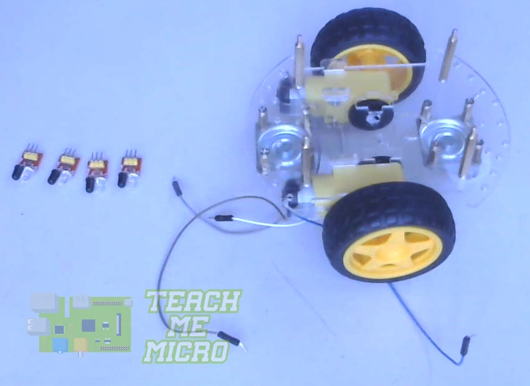
As you can see, I've soldered wires to the motor. These are male-male jumper wires with the other end cut off for easy soldering.
The chassis comes with two caster wheels and has holes for both but I found out that the front caster wheel tends to lift up the base, hence, not allowing the bigger wheels to touch the ground properly. So I had to remove it (can be seen in the video below).
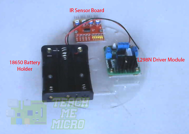
Step 2: Assembling the Robot Top
Next is to attach the rest of the components in the top part of the robot chassis. As I've mentioned, the top part was not meant to be used with the modules I've chosen for this project so I had to improvise a bit. I attached the battery holder, L298N module and IR sensor "motherboard" on one side:
I ran out of space! So I had to attach the Arduino UNO to the other side:
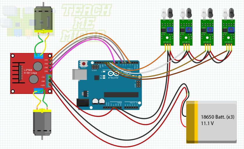
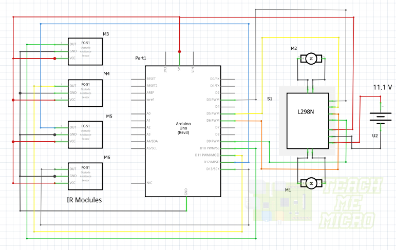
Step 3: Connect Some Wires
I used the following Fritzing and schematic diagrams for the wiring:
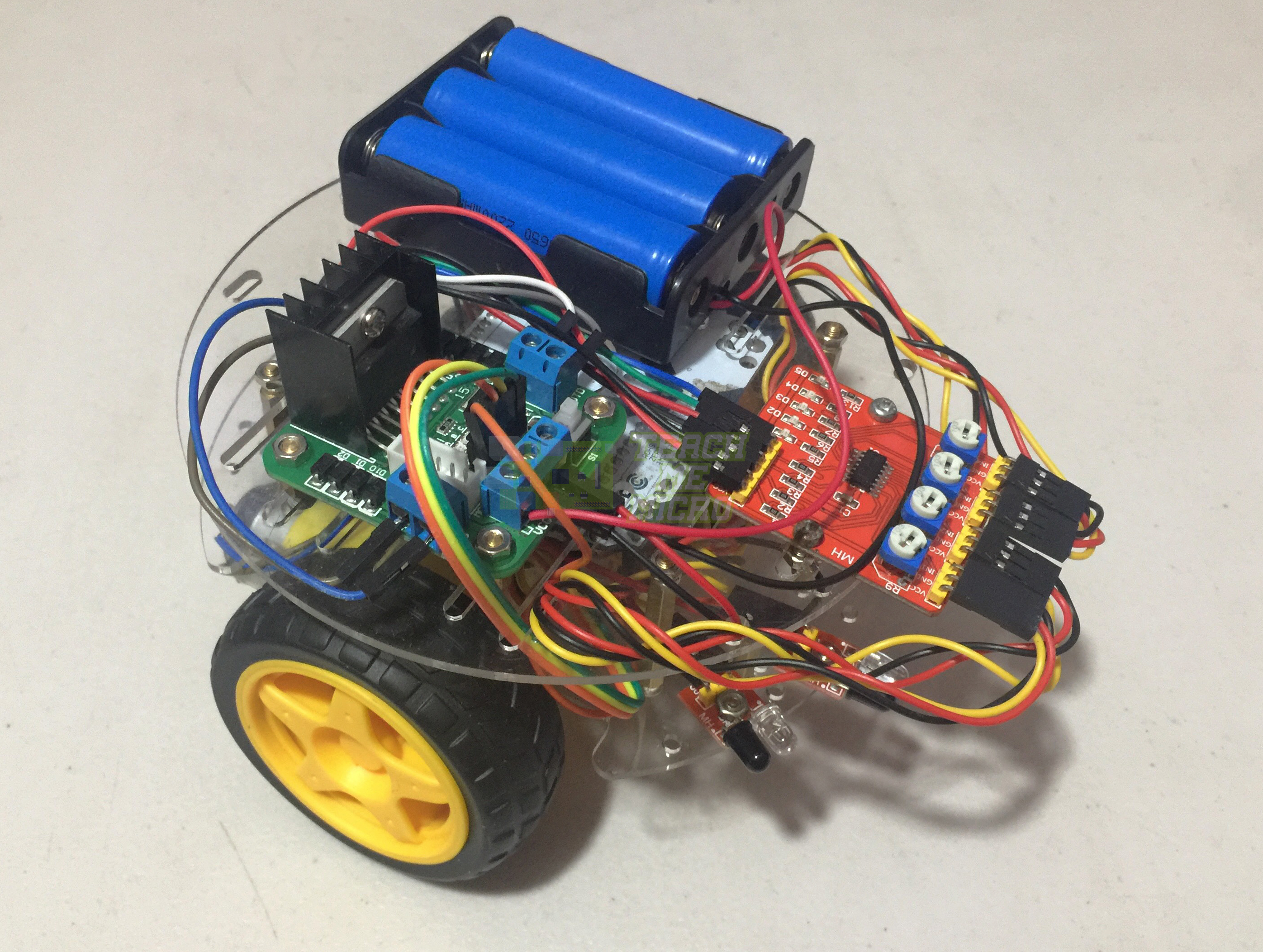
Step 4: Connect the Bottom and Top Parts
I used the extra holes on the top part for the wires to go through, making the wiring a bit tidier. The finished Arduino robot now looks like this:
Step 5: Upload the Code
The Arduino sketch for the robot is not that complicated. The idea is that the robot should go away from the obstacle detected by the IR sensors. For example, when the left most sensor is triggered, the robot must backpedal, turn right and then go forward.
/*
Obstacle Avoiding Arduino Robot Sketch
by Roland
www.teachmemicro.com/arduino-robot-obstacle-avoiding
*/

//Motor Driver Pins
int Motor_INA = 3;
int Motor_INB = 5;
int Motor_INC = 6;
int Motor_IND = 9;
//Sensor Pins
int Sensor_IN1 = 10;
int Sensor_IN2 = 11;
int Sensor_IN3 = 12;
int Sensor_IN4 = 13;

void setup() {
 pinMode(Motor_INA,OUTPUT);
 pinMode(Motor_INB,OUTPUT);
 pinMode(Motor_INC,OUTPUT);
 pinMode(Motor_IND,OUTPUT);

 pinMode(Sensor_IN1,INPUT);
 pinMode(Sensor_IN2,INPUT);
 pinMode(Sensor_IN3,INPUT);
 pinMode(Sensor_IN4,INPUT);
}

void goReverse(){
  analogWrite(Motor_INA,0);
  analogWrite(Motor_INB,50);
  analogWrite(Motor_INC,0);
  analogWrite(Motor_IND,50);
  delay(500);
}

void goRight(){
  analogWrite(Motor_INA,0);
  analogWrite(Motor_INB,0);
  analogWrite(Motor_INC,50);
  analogWrite(Motor_IND,0);
}

void goLeft(){
  analogWrite(Motor_INA,50);
  analogWrite(Motor_INB,0);
  analogWrite(Motor_INC,0);
  analogWrite(Motor_IND,0);
}

void stopBot(){
  analogWrite(Motor_INA,0);
  analogWrite(Motor_INB,0);
  analogWrite(Motor_INC,0);
  analogWrite(Motor_IND,0);
}

void goStraight(){
  analogWrite(Motor_INA,50);
  analogWrite(Motor_INB,0);
  analogWrite(Motor_INC,50);
  analogWrite(Motor_IND,0);
}
void loop() {
  delay(500);
  if(digitalRead(Sensor_IN1) == 0 || digitalRead(Sensor_IN2) == 0){
    goReverse();
    delay(100);
    stopBot();
    delay(100);
    goRight();
    delay(100);
    stopBot();
    delay(100);
    goStraight();
  }else if(digitalRead(Sensor_IN3) == 0 || digitalRead(Sensor_IN4) == 0){
    goReverse();
    delay(100);
    stopBot();
    delay(100);
    goLeft();
    delay(100);
    stopBot();
    delay(100);
    goStraight();
  }else if(digitalRead(Sensor_IN1) == 0 && digitalRead(Sensor_IN2) == 0 && digitalRead(Sensor_IN3) == 0 && digitalRead(Sensor_IN4) == 0){
    stopBot();
  }else{
    goStraight();
  }

}
The IR sensor is basically an IR LED and receiver pair. When something is in front of it, the radiation from the IR LED bounces back to the receiver. If nothing is in front, the receiver will receive nothing. This concept is a simple "on and off" scheme.
So to detect an obstacle, I only had to read the pin where an IR sensor is connected. If it's high, there's something there. Otherwise, there's nothing in front of the sensor.
To move forward, I need to rotate the wheels in the same direction. I wanted the robot to not move too fast. In order to control its speed, I used PWM to drive the motors through the L298N driver module. Producing PWM is just using analogWrite() but of course, I had to make sure that the Arduino pins for motor control are PWM pins.
Video
The video below shows the whole construction and assembly process as well as a demonstration on how the Arduino robot runs:
Got any questions, tips or reactions? Kindly comment below or create a thread on our community page!

