
The SIM800L is a cheap and portable GSM breakout board with all the capabilities of the larger SIM900 shields. In this Arduino SIM800L tutorial, I will help you with using this nifty device. Sending and receiving texts with your Arduino have never been easier!
Video Tutorial
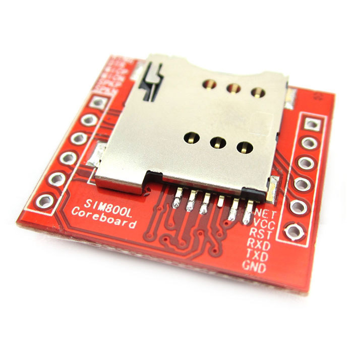
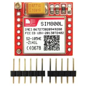
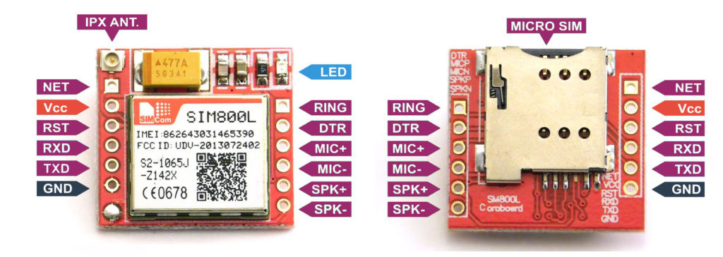
SIM800L Introduction
Here are the features of the SIM800L breakout board:
- 2G quad-band @ 850/900/1800/1900 MHz
- Receive and make calls using the speaker and microphone outputs
- Receive and send SMS
- Connect to the Internet via GPRS
- Listen to FM radio broadcasts
- Accepts AT Commands
Read more information from the SIM800L Datasheet.
Go to SIM900 Tutorial if you have that module instead
Powering the Board
Power requirements is probably the most common issue with the SIM800L. This board draws a maximum of 2 A with an input voltage of 3.7 V to 4.2 V. This means you must not connect its pins directly to a 5 V Arduino! It doesn't even run on 3.3 V. However, its TX and RX pins are 5V tolerant.
Some YouTube videos power their modules from the Arduino UNO's power pins which really doesn't work for me. When on USB port, the Arduino's 5V pin can supply a maximum of 450 mA and when on its DC Jack, about 800 mA. However, these might explain why their modules work:
- their Arduino's have internal regulators that drop the voltage to ~4.4-4.5 V when the SIM800L is connected
- they are very close to mobile network transmitters, which means the SIM800L doesn't need to draw too much power to establish a connection
Some also use a diode to drop the 5 V voltage to ~4.3 V (assuming a silicon diode). Maybe this would solve the voltage problem, but not the current problem.
The better approach is either to use a regulator or just have the SIM800L draw from a Li-Po battery.
If selecting a voltage regulator, I recommend the LM2596S regulator module.
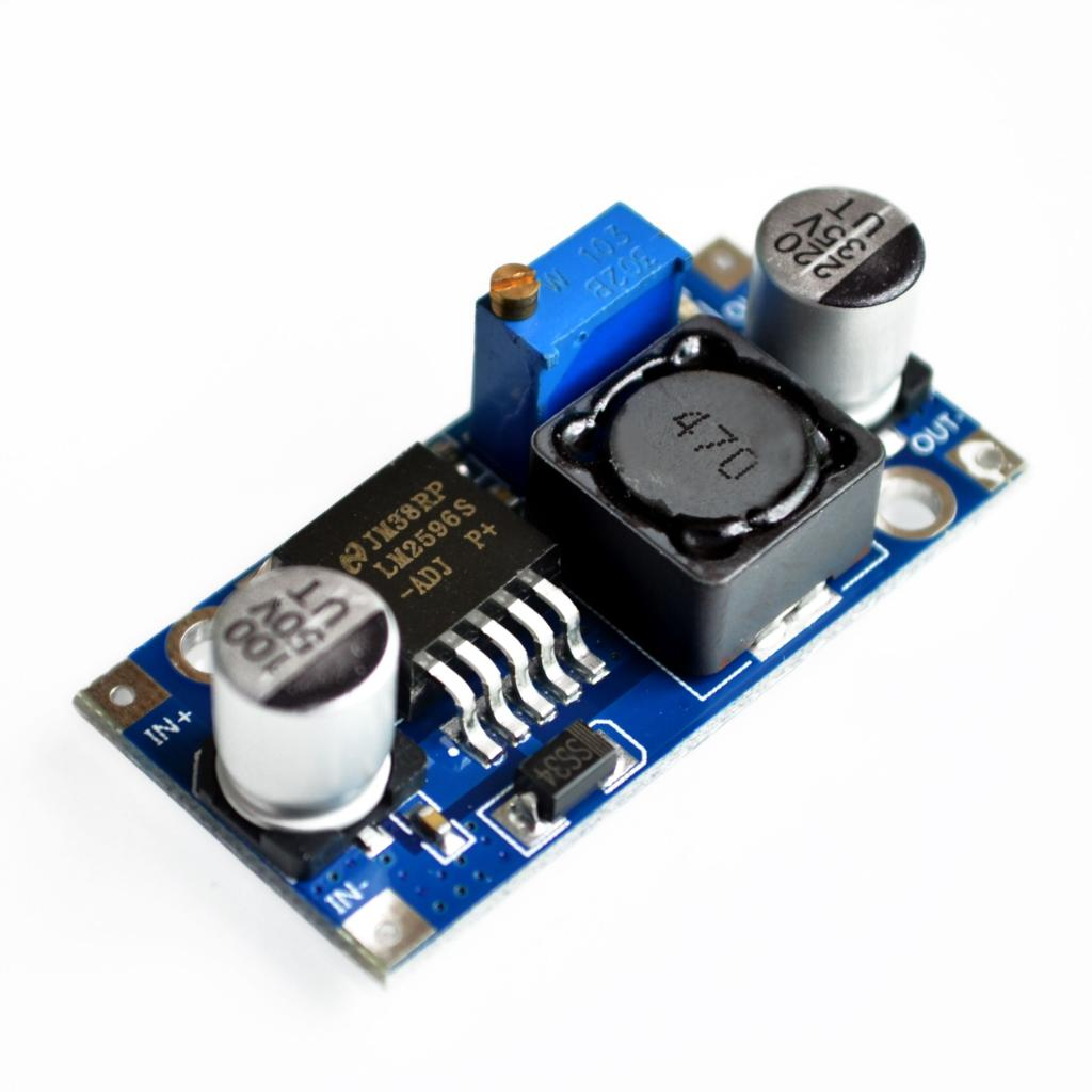
The LM2596S can provide a maximum 3 A to its load. You simply use a higher voltage in its input then adjust the on-board potentiometer to have 3.7 to 4.4 V for the SIM800L. Take note that the input voltage must be at least 1.5 V higher than the output.
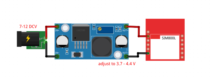
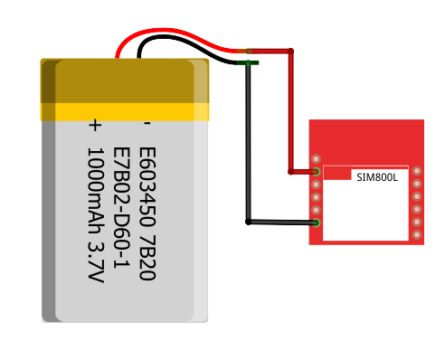
A Li-Po battery works well too, since they provide 3.7 V. I recommend Li-Po battery with higher ampere-hour ratings so that it can provide the SIM800L's current requirements. My network test project uses a battery to supply power to the SIM800L.
Connecting the SIM800L to Network
If the power to the SIM800L is enough, the on-board LED starts blinking. If there's not enough power, the LED blinks for about three seconds, then turns off.
The frequency of the blinking means something:
- Every second: searching for a network.
- Every three seconds: connected to a network.
- Twice per second: connected through GPRS.
Here's a video showing these LED indications:
Antennas are essential for this kind of module especially if your project is indoors. Without an antenna, there would not be enough transmitting power for the SIM800L to perform GSM services such as calls and SMS.
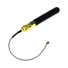
The image above is an outdoor whip antenna and I found this antenna to be more effective than the indoor helical antenna that comes with the SIM800L module:
Another type of antenna is the PCB antenna:
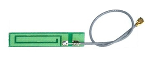
This type of antenna is cheaper and doesn't take much space as that of the whip antenna. Performance wise, the PCB antenna can be as good as the whip if the design is correct.
My recommendation is to use both the indoor helical antenna and either the whip or PCB antenna.
If you are still having trouble with the SIM800L, I suggest you try out my network test project. This helps you test out if the module is really connecting to a network or is getting enough power.
SIM800L and AT Commands
Like other modems, the SIM800L communicates through AT Commands. The Arduino sends these commands serially to the SIM800L and the latter replies via the same serial port.
The first command is the initial handshake command, which is simply:
AT
If the SIM800L is good to go, it should reply with:
OK
Other commands we can use to check the SIM800L is the signal quality test:
AT+CSQ
for which the module should reply something like this:
+CSQ:18,99
The first number is the Received Signal Strength Indicator (RSSI) which tells you about the network signal the module is receiving. A good RSSI is 31:
0 -> -113 dBm or less
1 -> -111 dBm
2...30 -> -109...-53 dBm
31 -> -51 dBm or greater
99 -> not known or not detectable
The second number is the Bit Error Rate (BER) which is the number of bit errors divided by the total number of bits received by the module. Possible values are 0 to 7 or 99:
0 -> BER < 0.2%
1 -> 0.2% < BER < 0.4%
2 -> 0.4% < BER < 0.8%
3 -> 0.8% < BER < 1.6%
4 -> 1.6% < BER < 3.2 %
5 -> 3.2% < BER < 6.4%
6 -> 6.4% < BER < 12.8%
7 -> 12.8% < BER
99 -> not known or not detectable
The higher the BER, the more bit errors. Thus, the ideal BER value should be closer to 0.
The network registration test can tell you if the SIM800L is ready to send/receive SMS or make calls:
AT+CREG?
The module will reply with two numbers:
+CREG: 1,1
Where the 1st number is:
0 not registered, MT is not currently searching a new operator to register to
1 registered, home network
2 not registered, but MT is currently searching a new operator to register to
3 registration denied
4 unknown (e.g. out of GERAN/UTRAN/E-UTRAN coverage)
5 registered, roaming
6 registered for "SMS only", home network (applicable only when indicates E-UTRAN)
7 registered for "SMS only", roaming (applicable only when indicates E-UTRAN)
8 attached for emergency bearer services only (see NOTE 2) (not applicable)
9 registered for "CSFB not preferred", home network (applicable only when indicates E-UTRAN)
10 registered for "CSFB not preferred", roaming (applicable only when indicates E-UTRAN)
and the second number is:
0 GSM
1 GSM Compact
2 UTRAN
3 GSM w/EGPRS
4 UTRAN w/HSDPA
5 UTRAN w/HSUPA
6 UTRAN w/HSDPA and HSUPA
7 E-UTRAN
The ideal reply from a SIM800L to function well (including data) is:
+CREG: 1,3
+CREG: 1,4
+CREG: 1,5
+CREG: 1,6
Note that results may vary with your location.
To begin sending commands to the SIM800L, wire it to the Arduino UNO as shown:
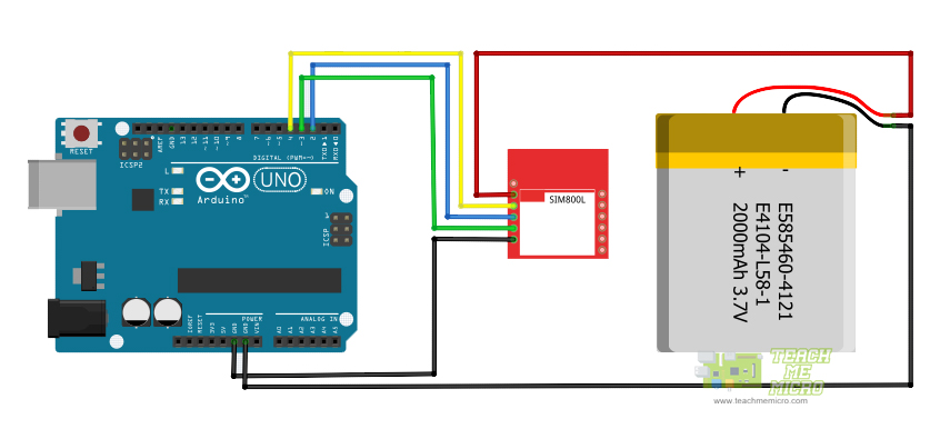
Here, I am using a Li-Po battery. If you can't get one like this, use LM2596S instead as seen in the previous section.
The Arduino UNO has a hardware serial port but it's the one used for sending code to it via USB. Instead, we use a serial port emulated through software.
First we include the library and then create a Software Serial object:
#include <SoftwareSerial.h>

SoftwareSerial sim800l(3, 2);
We need to know the reply of the SIM800L. So we initialize both hardware and serial ports in order to print the replies via serial monitor:
Serial.begin(9600);
sim800l.begin(9600);
To send a command, we do:
sim800l.println("AT");Or we can just send the commands via serial monitor. To do that and also read the reply from the SIM800L, we place this inside loop():
while (Serial.available()){
   delay(1);
   sim800l.write(Serial.read());
}

while (sim800l.available()){
   Serial.write(sim800l.read());
}
Here is the full sketch for the AT command test:
#include <SoftwareSerial.h>

SoftwareSerial sim800l(3,2);

void setup(){
  Serial.begin(9600);
  sim800l.begin(9600);
}

void loop(){
  while (Serial.available()){
    delay(1);
    sim800l.write(Serial.read());
  }

  while (sim800l.available()){
    Serial.write(sim800l.read());
  }
}
Here's how the SIM800L is responding with AT Commands:
The FONA Library
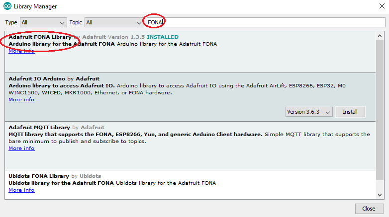
While we can maximize the functions of the SIM800l through AT commands, it is much easier to use an existing library instead. The library I recommend is Adafruit's FONA library. Download it here and extract it on Documents > Arduino > libraries. Or you can go to Sketch > Include Library > Manage Libraries and type "FONA" in the search bar.
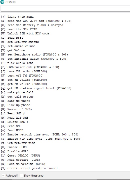
The library comes with a number of examples. The FONA_test sketch gives us access to all the SIM800l functions! If you upload the sketch and use the same wiring diagram, you'll see this on the serial monitor:
Here's a short video showing how I sent an SMS using this library:
SMS Sending
The FONA library has a simple sendSMS() function that accepts the number and message as parameters and returns true if the message was sent through the network successfully. Here's an example code that sends one SMS:
#include <SoftwareSerial.h>
#include "Adafruit_FONA.h"

#define FONA_RX 2
#define FONA_TX 3
#define FONA_RST 4

char replybuffer[255];

SoftwareSerial sim800l = SoftwareSerial(FONA_TX, FONA_RX);

Adafruit_FONA gsm = Adafruit_FONA(FONA_RST);

//uint8_t readline(char *buff, uint8_t maxbuff, uint16_t timeout = 0);

void setup() {
  Serial.begin(9600);
  sim800l.begin(9600);
  if (! gsm.begin(sim800l)) {
    Serial.println(F("Couldn't find SIM800L!"));
    while (1);
  }

   char sendto[21] = "09173234058";
   char message[141] = "Hello from SIM800L";
   gsm.sendSMS(sendto, message);
   delay(1000);
}

void loop() {}
Upload this sketch to your Arduino and open serial monitor to send SMS.
Let me explain the sketch above. Let's start with this:
#define FONA_RX 2
#define FONA_TX 3
#define FONA_RST 4
This part declares that the RX, TX and RST pins of the SIM800L must be connected to pin 2, 3 and 4 of the Arduino.
SoftwareSerial sim800l = SoftwareSerial(FONA_TX, FONA_RX);

Adafruit_FONA gsm = Adafruit_FONA(FONA_RST);
The lines above assigns the RX and TX pins as software serial pins. This is done so that the Arduino's hardware serial port remains to be used with the serial monitor. The FONA object (gsm) is then initialized with the RST pin as parameter.
Check out my GPRS tutorial to learn how to use the SIM800 module to connect to the Internet
The SIM800L is checked using the following sequence:
if (! gsm.begin(sim800l)) {
   Serial.println(F("Couldn't find SIM800L!"));
   while (1);
}
If "Couldn't find SIM800L!" appears in the serial monitor the program goes to an infinite loop and therefore will not continue.
char sendto[21] = "09171234567";
char message[141] = "Hello from SIM800L";
gsm.sendSMS(sendto, message);
delay(1000);
This part is the SMS sending part. The message "Hello from SIM800L" will be sent to the number "09171234567" when the Arduino starts.
Reading SMS
How about sending SMS to the SIM800L and reading it? We add a function for reading SMS:
void readSMS(int smsn){
          uint16_t smslen;
          if (! gsm.getSMSSender(smsn, replybuffer, 250)) {
            Serial.println("Failed!");
            return;
          }
          Serial.print(F("FROM: "));
          Serial.println(replybuffer);

          Serial.print(F("\n\rReading SMS #")); Serial.println(smsn);
          if (!gsm.readSMS(smsn, replybuffer, 250, &smslen)) {  // pass in buffer and max len!
            Serial.println(F("Failed!"));
            return;
          }
          Serial.println(replybuffer);
}
The function getSMSSender() returns true and places the SMS sender number to the replybuffer, while the readSMS() function returns true and places the SMS to that same buffer.
To use the function, specify which SMS you want to read:
readSMS(1);This code reads the SMS at location #1. The disadvantage of this code is you can't read the latest SMS because they are not indexed according to delivery time. If your applications requires to read the latest SMS, I suggest you use the FONA_SMS_response example sketch from the FONA library.
Making a Call
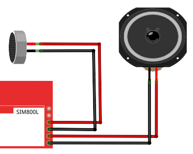
To make a call, we must attached a speaker to the SPKRP and SPRKRN terminals of the SIM800L and an electret microphone to the MICP and MICN terminals.
Then we add another function:
void callNumber(char * number){
   if (!gsm.callPhone(number)) {
       Serial.println(F("Failed"));
   } else {
       Serial.println(F("Sent!"));
   }
}
Calling a number is possible through the callPhone() function from the library. Moreover, this function returns true if the call is successfull. The number to be called is the parameter for this function.
To use this function, just pass the number to be called like this:
char callNum[21] = "09171234567";
callNumber(callNum);
Receiving a Call
Receiving a call is a bit more complicated because there must be an interrupt trigger to acknowledge the call. This is what the example IncomingCall sketch does:
#include <SoftwareSerial.h>
#include "Adafruit_FONA.h"

#define FONA_RX            3
#define FONA_TX            4
#define FONA_RST           5

#define FONA_RI_INTERRUPT  0

SoftwareSerial fonaSS = SoftwareSerial(FONA_TX, FONA_RX);

Adafruit_FONA fona = Adafruit_FONA(FONA_RST);

void setup() {
  Serial.begin(115200);
  Serial.println(F("FONA incoming call example"));
  Serial.println(F("Initializing....(May take 3 seconds)"));
  fonaSS.begin(4800); // if you're using software serial
  if (! fona.begin(fonaSS)) {           // can also try fona.begin(Serial1)
    Serial.println(F("Couldn't find FONA"));
    while (1);
  }
  Serial.println(F("FONA is OK"));

  if(fona.callerIdNotification(true, FONA_RI_INTERRUPT)) {
    Serial.println(F("Caller id notification enabled."));
  }
  else {
    Serial.println(F("Caller id notification disabled"));
  }
}

void loop(){
  char phone[32] = {0};
  if(fona.incomingCallNumber(phone)){
    Serial.println(F("RING!"));
    Serial.print(F("Phone Number: "));
    Serial.println(phone);
  }
}
The first thing that is noticeable is the change in the pin assignments for RX, TX and RST. This is because the D2 pin of the Arduino is the default interrupt pin. The SIM800L uses this pin to interrupt the Arduino whenever there is an incoming call. Thus, connecting the D2 pin to the SIM800L's RING pin (above the DTR pin, if its not visible in yours) is a must.
There's also an option to enable or disable Caller ID notification. Cool.
There are other options in the FONA library including reading the signal level of the GSM network, scanning FM networks, and enabling GPRS to connect to the Internet! I'll explore these features on my next post so stay tuned!
 Buy Chip SIM800L Modules at AliExpress
