
A finite state machine (FSM) is a theoretical machine that only has one action or state at a time. The machine may go from one state to another if there are inputs (or one input) that triggers the state change.
In this article, I will guide you on how to implement an Arduino state machine for your project. Using state machines will not necessarily make your Arduino sketch execute faster; state machines are just models for having well-organized code. Nevertheless, using FSM may reduce both your coding workload and chances of errors.
Defining a State Machine
A finite state machine or simply state machine is often presented in a state diagram. An example of such diagram is shown below:
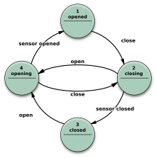
The nodes in the diagram are states while the arrows are transitions. We may read the diagram by the sequence of its states, following the direction of the arrows. Here, the first state is opened and the last state is opening.
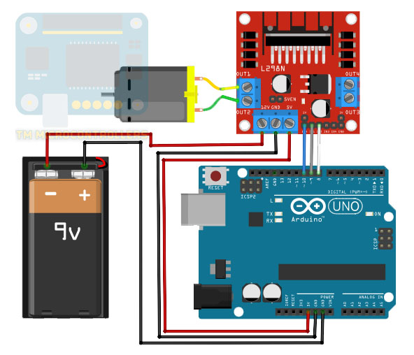
I think it's best to explain FSM using an example. Let's say we have a motor connected to an Arduino. A driver to control a motor would be added in the setup as shown:
The motor may have four states: start, stop, clockwise, and counterclockwise. The inputs are strings sent by the user through the serial monitor. The strings are "START", "STOP", "CW" and "CCW", corresponding to the each of the states.
The initial state of the motor is stop. When it is at this state, it accepts only one input: "START". When this string is received, the motor transitions to the start state. If the user sends a string "CW" at the start state, then the motor goes to the clockwise state. In the clockwise state, the motor may accept a "STOP" input string. The same is true if the user sends a "CCW" at the start state of the motor.
The state diagram now is shown below:
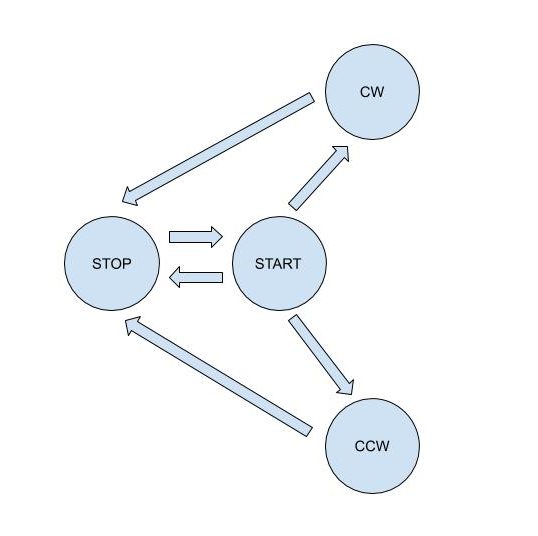
As the state diagram indicates, the motor cannot go from a stop state to a clockwise or counterclockwise state because of the direction of arrows. Similarly, the motor cannot go from a clockwise state to a counter-clockwise state and vice versa. The motor may go from start to stop directly.
Here, all these state transitions are defined by the user and not due to physical limitations. However in real situations, the state transitions are most likely because of system design.
Coding an Arduino State Machine
Now that we have a clear list of states and inputs, it's time to put them in an Arduino sketch. Here we'll be using the state machine library.
First we include the aforementioned library:
#include <FiniteStateMachine.h>
Then we define each state with functions as parameters. The function (which is somewhere in the sketch) executes when the machine is at the given state.
State START = State(startMotor);
State STOP = State(stopMotor);
State CW = State(turnClockwise);
State CCW = State(turnCounterClockwise);
Next, we create a state machine object:
FSM Motor = FSM();
This object may have a parameter that points to the initial state. If we want the motor to stop at startup, this is how we initiate the state machine object:
FSM Motor = FSM(STOP);
To start the state machine, we use the update() function. This function could be anywhere but for this example, it's inside loop() since the machine regularly changes states.
void loop(){
  ...
  Motor.update();
}
Specifying the next state of the machine is simply:
Motor.transitionTo(NAME OF STATE);
Here, the name of state can be START, STOP, CW or CCW.
The library also provides other functions such as getting the current state:
Motor.getCurrentState();
This function returns an object of type State.
You can also check if the machine is in a specific state:
Motor.isInState(START);
The line above will return true if the present state is the START state. Otherwise, it returns false.
Of course for our example, we still need to add the part where Arduino receives input strings from the serial port and how to make the motor do what we want. Let's have that at the end of this article.
Concurrent State Machines
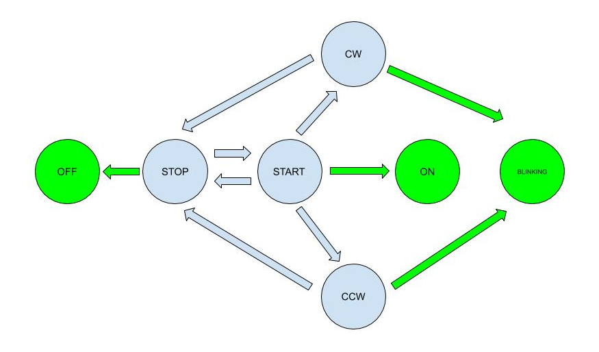
Now let's add another state machine to the mix. We'll use a LED that constantly blinks while the motor is in the clockwise and counterclockwise states. If the motor is in the stop state, the LED is turned off. Alternatively, the LED is on when the motor is in the start state. The LED therefore has three states: blinking, on and off. These three states have no direct relationship to each other but rather to the states of the motor machine.
Our new state diagram is shown below. Blue nodes are for the motor while green nodes are for the LED.
Because of the second object, we now add a second state machine in our sketch. But before that, we define the states of the LED:
//LED states
State ON = State(turnOnLED);
State OFF = State(turnOffLED);
State BLINK = State(blinkLED);
Then we initiate the new state machine object:
FSM LED = FSM(OFF);
Here we assign the initial state to be OFF.
The LED only blinks at specific states of the motor, so we modify the function associated with the motor states to include the control of the LED states.
void startMotor(){
  //turn motor clockwise
  ...
  LED.transitionTo(ON);
}

void stopMotor(){
  //turn motor clockwise
  ...
  LED.transitionTo(OFF);
}
Here we put the transitionTo() function to the motor states where we want the LED to do something. However, the LED blinking state is different since it's a continuous state. We put that transition inside loop():
if(Motor.isInState(CCW) || Motor.isInState(CW)){
    LED.transitionTo(BLINK);
    LED.update();
}
Now let’s create a full, working Arduino sketch with state machines. I borrowed parts of the code I did in my L298N article for controlling the motor. I also added a way to receive strings from the serial port.
#include <FiniteStateMachine.h>

//define states and working functions
//motor states
State START = State(startMotor);
State STOP = State(stopMotor);
State CW = State(turnClockwise);
State CCW = State(turnCounterClockwise);
//LED states
State ON = State(turnOnLED);
State OFF = State(turnOffLED);
State BLINK = State(blinkLED);

//initiate state machines
FSM Motor = FSM(STOP);
FSM LED = FSM(OFF);

//define motor controller pins
#define EnA 10
#define In1 9
#define In2 8

//for serial event
String inputString = "";         // a String to hold incoming data
bool stringComplete = false;  // whether the string is complete

void setup() {
 // All motor control pins are outputs
  pinMode(EnA, OUTPUT);
  pinMode(In1, OUTPUT);
  pinMode(In2, OUTPUT);
 // Use serial monitor
  Serial.begin(9600);
 // Use on-board LED
  pinMode(LED_BUILTIN, OUTPUT);
 // reserve 200 bytes for the inputString:
  inputString.reserve(200);
}

void loop() {
 // print the string when a newline arrives:
 if (stringComplete) {
    Serial.println(inputString);
    //set motor state depending on serial string
    if(inputString.equals("START\n")){
      if(Motor.isInState(STOP)){
        Serial.println("Start!");
        Motor.transitionTo(START);
      }
    }else if(inputString.equals("STOP\n")){
      if(Motor.isInState(START) || Motor.isInState(CW) || Motor.isInState(CCW)){
        Serial.println("Stop!");
        Motor.transitionTo(STOP);
      }
    }else if(inputString.equals("CW\n")){
      if(Motor.isInState(START)){
        Serial.println("Clockwise!");
        Motor.transitionTo(CW);
      }
    }else if(inputString.equals("CCW\n")){
      if(Motor.isInState(START)){
        Serial.println("Counter Clockwise!");
        Motor.transitionTo(CCW);
      }
    }else{;}
    // clear the string:
    inputString = "";
    stringComplete = false;

    // Run state machine
    Motor.update();
  }
  //if motor is turning CW or CCW, keep the LED blinking
  if(Motor.isInState(CCW) || Motor.isInState(CW)){
      LED.transitionTo(BLINK);
      LED.update();
  }
}

void serialEvent(){
  while (Serial.available()) {
    // get the new byte:
    char inChar = (char)Serial.read();
    // add it to the inputString:
    inputString += inChar;
    // if the incoming character is a newline, set a flag so the main loop can
    // do something about it:
    if (inChar == '\n') {
      stringComplete = true;
    }
  }
}

void turnClockwise(){
   //turn motor clockwise
   digitalWrite(In1, HIGH);
   digitalWrite(In2, LOW);
   delay(1000);  //delay for a second
}

void turnCounterClockwise(){
   //turn motor clockwise
   digitalWrite(In1, LOW);
   digitalWrite(In2, HIGH);
   delay(1000);  //delay for a second
}

void startMotor(){
   //start motor
   digitalWrite(EnA, HIGH);
   LED.transitionTo(ON);
   LED.update();
}


void stopMotor(){
   //stop motor
   digitalWrite(EnA, LOW);
   LED.transitionTo(OFF);
   LED.update();
}

void turnOffLED(){
   //turn off LED
   digitalWrite(LED_BUILTIN, LOW);
}

void turnOnLED(){
   //turn on LED
   digitalWrite(LED_BUILTIN, HIGH);
}

void blinkLED(){
   //blink LED
   digitalWrite(LED_BUILTIN, !digitalRead(LED_BUILTIN));
   delay(500);
}
What this code does is wait for the string inputs from the serial monitor and will proceed to the corresponding state. It only accepts certain inputs depending on the current state of the machine, according to the arrows indicated in the state diagram.
That's it for creating an Arduino state machine. If you have any questions, suggestions and reactions to this article, please drop a comment below!

