
In my previous Arduino Interrupt tutorial, I showed how to use the external and pin change interrupts for the ATMega328p-based Arduinos. There, I showed an example where pressing a button halts the normal program execution at any time and serves another routine (Interrupt Service Routine or ISR). In this article, we’ll look at how to use Arduino timer interrupt.
Arduino Timers
The Arduino UNO’s ATMega328p has 3 timers at its disposal: Timer0, Timer1 and Timer2. Both Timer0 and Timer2 are 8-bit timers (can count from 0 to 255) while Timer1 is a 16-bit timer (0 to 65535).
Arduino timer interrupt programming is possible for each timer, besides providing timing and pulse counting. Also, these timers make PWM generation possible.
For this tutorial, I’ll only show how to use Timer2 and Timer1 for interrupt since Timer0 is already used by millis(). Specifically, I will use Timer2 for timer overflow and compare interrupts and Timer1 for capture interrupt.
Timer Overflow Interrupt
Just like the other timers, there are three ways to use Timer2 for interrupts. The first way is by checking if the timer has overflowed.
Timer overflow is a condition where the timer has counted beyond its maximum number. For Timer2, overflow occurs when the count goes beyond 255, bringing it back to 0.
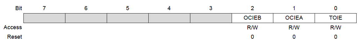
Setting the TOIE bit on each timer’s interrupt mask register, TIMSKx, enables timer overflow interrupt. The 'x' here is the timer number and so for Timer2, the register is TIMSK2:
Exactly when the overflow occurs depends on the oscillator frequency and the clock divisor. Hence, this is the Timer2 overflow time formula:
The Arduino UNO board has a 16 MHz oscillator and the clock divisor is 64 by default. So for Timer2, the time it will overflow will be:
This means the interrupt triggers very close to 1 millisecond or about 1 kHz of frequency.
How do we know when the interrupt occurred in sketch? When Timer2 overflows, the interrupt vector TIMER2_OVF is read by the ATMega328p’s CPU. Therefore, the ISR would be like this:
ISR(TIMER2_OVF_vect){
        //do something here
}
Using Timer Overflow in Arduino Sketch
I made a sketch that blinks the on-board LED (the one connecting to D13) on the Arduino UNO using timer overflow. I adjusted the overflow frequency because 1 millisecond would be too fast for our eyes to see. To slow down the timer, we need to increase the divisor value. This is done by writing to the TCCR2B register:
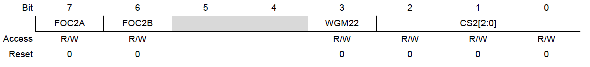
Bits 2 to 0 (CS2) are the ones we need to manipulate to change the clock divisor. These are the bit values and the corresponding divisor:
|
CS2 [2:0] |
Divisor |
|
001 or 0x01 |
1 |
|
010 or 0x02 |
8 |
|
011 or 0x03 |
32 |
|
100 or 0x04 |
64 |
|
101 or 0x05 |
128 |
|
110 or 0x06 |
256 |
|
111 or 0x07 |
1024 |
For example, if we will use 1024 as divisor, this should be the value of the TCCR2B register:
TCCR2B = (TCCR2B & B11111000) | 0x07 //use mask so that only the least three
                                     //significant bits are affected
Also I’ve mentioned that to enable timer overflow, we must set the TOIE bit on TIMSK2 register:
TIMSK2 = (TIMSK2 & B11111110) | 0x01 //use mask so that only the least
                                     //significant bit is affected
[the_ad id="3059"]
Finally, here’s the full sketch:
const int ledPin = 13;
volatile byte state = LOW;


void setup() {
   pinMode(ledPin, OUTPUT);
   TIMSK2 = (TIMSK2 & B11111110) | 0x01;
   TCCR2B = (TCCR2B & B11111000) | 0x07;
}


void loop() {
   digitalWrite(ledPin, state);
}


ISR(TIMER2_OVF_vect){
   state = !state;
}
Upload this to your Arduino UNO board and the on-board LED should be blinking at a rate equal to:
That speed should be enough for our eyes to see.
Timer Compare Interrupt
The next way to use Arduino timer interrupt is by comparing the timer count to a specific value. Every time the timer’s count is equal to that value, the interrupt occurs. This is called Timer Compare Interrupt.
When using timer overflow interrupt, the interrupt triggers after 255 counts. In compare mode, the interrupt trigger to any count value that we set! Not only that, but you can compare the timer to two values.
There are two possible comparisons, A and B. For Compare A, the timer value is compared to the OCRxA register where 'x' is the timer number. Thus, for Timer2 the register is OCR2A.
For example, I want the interrupt to trigger after 128 counts. Thus, this must be the value of OCR2A:
OCR2A = 128;
For Compare B, the value to be compared must be written to the OCR2B register. So let’s say I want another interrupt to trigger at count 200, then:
OCR2B = 200;
To know which between Compare A and Compare B triggered, we refer to their corresponding vectors: TIMER2_COMPA and TIMER2_COMPB.
Of course, we still need to enable the compare interrupt first. Setting bits OCIEA and OCIEB on the TIMSK2 register does this:
So this should be the value of TIMSK2 when using Timer Compare Interrupt:
TIMSK2 = (TIMSK2 & B11111001) | 0x06; //again, using a mask to protect other bits
Implementing Timer Compare
Now we will modify the first sketch above to use the Timer Compare interrupt. Here’s the new sketch:
const int ledPin = 13;
volatile byte state = LOW;

void setup() {
   pinMode(ledPin, OUTPUT);
   TIMSK2 = (TIMSK2 & B11111001) | 0x06;
   TCCR2B = (TCCR2B & B11111000) | 0x07;
   OCR2A = 128;
   OCR2B = 200;
}

void loop() {
   digitalWrite(ledPin, state);
}

ISR(TIMER2_COMPA_vect){
   state = LOW;
}

ISR(TIMER2_COMPB_vect){
   state = HIGH;
}
The result of the sketch is the on-board LED turning off when the Timer2 count is 128 and then turning on when the count is 200.
Timer Capture Interrupt
Finally, we have the Timer Capture Interrupt. However, this Arduino timer interrupt can only be used with Timer1 on the Arduino UNO so let’s switch timers.
A capture event occurs when a pulse is read on the ICP1 pin or D8:
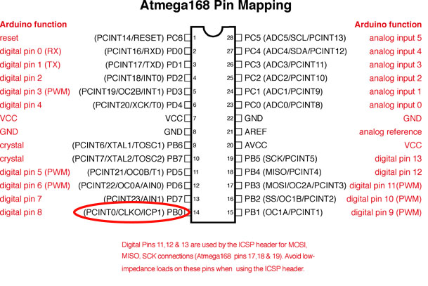
The capture event can be further specified to whether the pulse is rising or falling through TCCR1B:
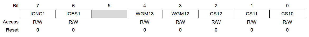
If the ICES1 bit (bit 6) above is set, the capture event occurs every rising edge of the pulse. Otherwise, the capture occurs on falling edge.
Another interesting part of TCCR1B are the last three bits: CS12, CS11, CS10. These bits set the divisor for the Timer1 counter.
|
CS12, CS11, CS10 |
Divisor |
|
001 or 0x01 |
1 |
|
010 or 0x02 |
8 |
|
011 or 0x03 |
64 |
|
100 or 0x04 |
256 |
|
101 or 0x05 |
1024 |
|
110 or 0x06 |
External clock source on T1, falling edge |
|
111 or 0x07 |
External clock source on T1, rising edge |
For now, we will not use a divisor so these three bits is equal to 0x01.
So let’s say we want the capture to happen every rising edge, then this should be the value of TCCR1B:
TCCR1B = (TCCR1B & B10111000) | 0x41;
The register TCNT1 counts every pulse. To accommodate a large number of pulses, the TCNT1 is made out of two 8-bit registers, TCNT1L and TCNT1H. In short, 65535 pulses on D8 can be counted.
The value of TCNT1 is then copied to register ICR1 and a flag located at TIFR1 (ICF1) is set. This flag is automatically cleared.
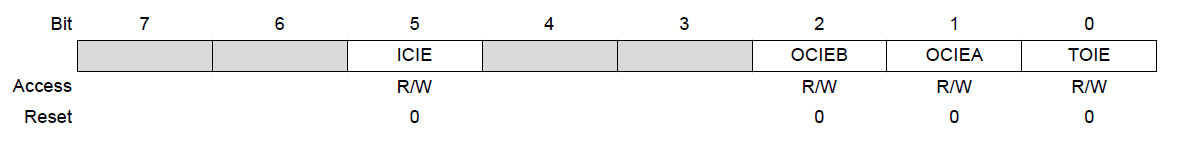
Meanwhile, if bit ICEI of register TIMSK1 is set, the TIMER1_CAPT vector is read by the CPU everytime a capture occurs.
Therefore, the ISR() should be:
ISR(TIMER1_CAPT_vect){
   //do something here
}
Using Timer Compare in a Sketch
We can simulate the timer capture interrupt by placing a button on D8. Pressing then depressing the button is like sending out a pulse to this pin. We shall use the on-board LED again as a visual indicator that the interrupt triggered.
This will be the full sketch:
void setup() {
   pinMode(ledPin, OUTPUT);
   pinMode(8, INPUT);
   Serial.begin(9600);
   TIMSK1 = (TIMSK1 & B11011111) | 0x20; //enable timer capture interrupt
   TCCR1B = (TCCR1B & B10111000) | 0x41; //falling edge, no prescale
}

void loop() {
   digitalWrite(ledPin, state);
}


ISR(TIMER1_CAPT_vect){
   int t = ICR1; //must be read first, according to datasheet
   Serial.println(t);
   state = !state;
}
The on-board LED should turn on/off when the button is pressed and turn off/on when the button is pressed again. Also, I wrote the value of the counter (ICR1) on the serial monitor in order to know that Timer1 is indeed counting.
We can go further with timer capture interrupt by sending pulses to D8 and counting the pulses per period of time. This will lead to a simple frequency counter. I will be building that project very soon.
Using a Timer Interrupt Library
Update
If manipulating registers is hard for you, there is the TimerOne arduino library that you can use. Here is an example sketch that uses this library:
#include <TimerOne.h>

void setup()
{
  // Initialize the digital pin as an output.
  // Pin 13 has an LED connected on most Arduino boards
  pinMode(13, OUTPUT);

  Timer1.initialize(100000); // set a timer of length 100000 microseconds (or 0.1 sec - or 10Hz => the led will blink 5 times, 5 cycles of on-and-off, per second)
  Timer1.attachInterrupt( timerIsr ); // attach the service routine here
}

void loop()
{
  // Main code loop
  // TODO: Put your regular (non-ISR) logic here
}

/// --------------------------
/// Custom ISR Timer Routine
/// --------------------------
void timerIsr()
{
    // Toggle LED
    digitalWrite( 13, digitalRead( 13 ) ^ 1 );
}
The sketch above flashes a LED on D13 every time the timer overflows.
Here, the timer interrupt is initialized to timeout at 0.1 second:
Timer1.initialize(100000); // set a timer of length 100000 microseconds (or 0.1 sec - or 10Hz => the led will blink 5 times, 5 cycles of on-and-off, per second)
Timer1.attachInterrupt( timerIsr ); // attach the service routine here
The timerIsr, the interrupt handler, is where the LED state is toggled:
void timerIsr() {
 // Toggle LED
 digitalWrite( 13, digitalRead( 13 ) ^ 1 );
}
I hope you found this tutorial on Arduino Timer Interrupt helpful. Also, kindly drop a comment below if you have questions related to this topic.

