
Turbidity refers to the haziness of a fluid caused by the increased number of very tiny particles which, individually, is invisible to us. Moreover, turbidity measurement is important in testing the quality of water. This Arduino turbidity sensor tutorial provides a guide on how to implement this setup using a specialized turbidity sensor module.
Introduction to Turbidity Sensor
The concept of DFRobot’s Turbidity Sensor is based on Tyndall effect. This effect describes the scattering of light projected into a liquid with suspended particles. Basically, the greater the number of particles, the more the light will be scattered.
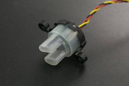
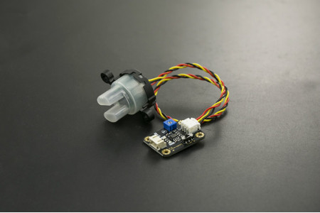
This sensor module consists of an amplifier board and a sensor:
The module is to be connected to Arduino using three pins only: VCC, GND and SIGNAL. Here is an example Fritzing diagram where the turbidity sensor is connected to an Arduino UNO:
Important note: there is a correct way to connect the wire from the amplifier board to the turbidity sensor:
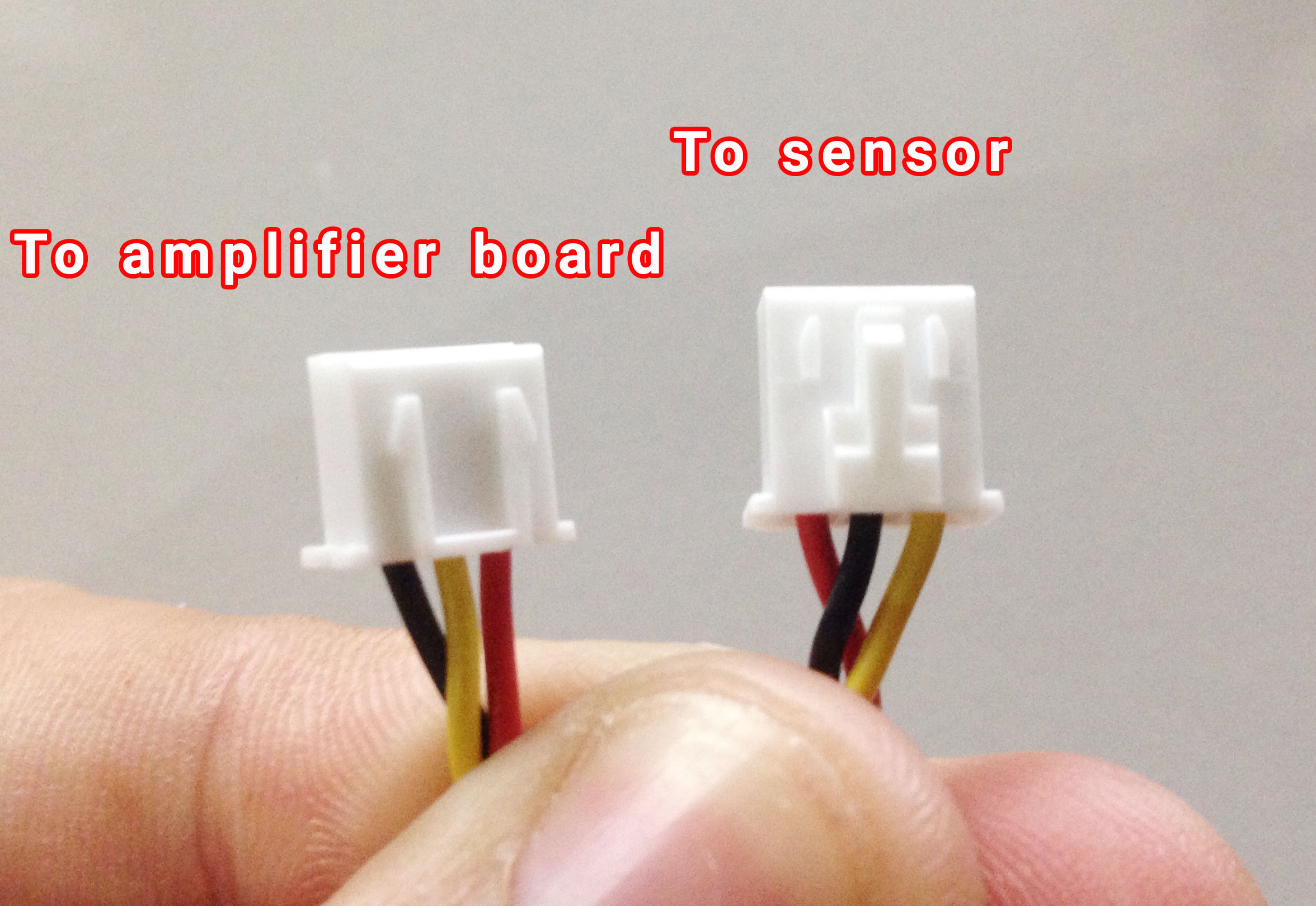
You need to connect the wire the right way or the sensor won’t work! I’ve spent hours wondering why nothing is working until I learned about this.
The turbidity sensor contains a light transmitter and receiver. At clear waters, light scattering is minimum and so the light receiver receives the most amount of light. As turbidity of the water increases, the light receiver receives less and less light. The sensor triggers when the light received is below a certain threshold.
Interestingly enough, there is an “analog-digital” switch on the amplifier board which supposedly switches between analog mode and digital mode. The official wiki says that when in analog mode, the output value decreases at high turbidity. When in digital mode, the output pin goes high when the turbidity reaches a threshold value, set by the on-board potentiometer.
When your objective is just to detect when the water is turbid enough, then use digital mode. If you want to measure the turbidity levels, then you need to use analog mode.
Using the Turbidity Sensor with Arduino
The same official wiki gave this graph with an equation that relates the voltage from the sensor to turbidity:
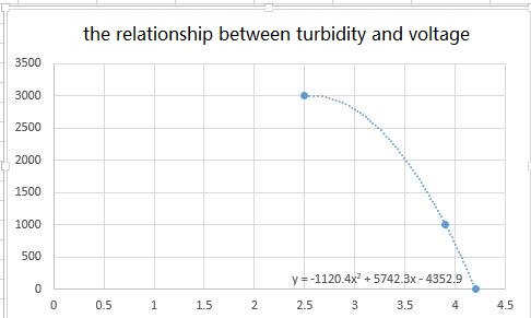
However, this equation (presumably acquired through curve fitting) is only applicable when the sensor gives out around approximately 4.2 volts at no turbidity. Mine didn’t give out 4.2 V so I had to pry open the sensor and found this:
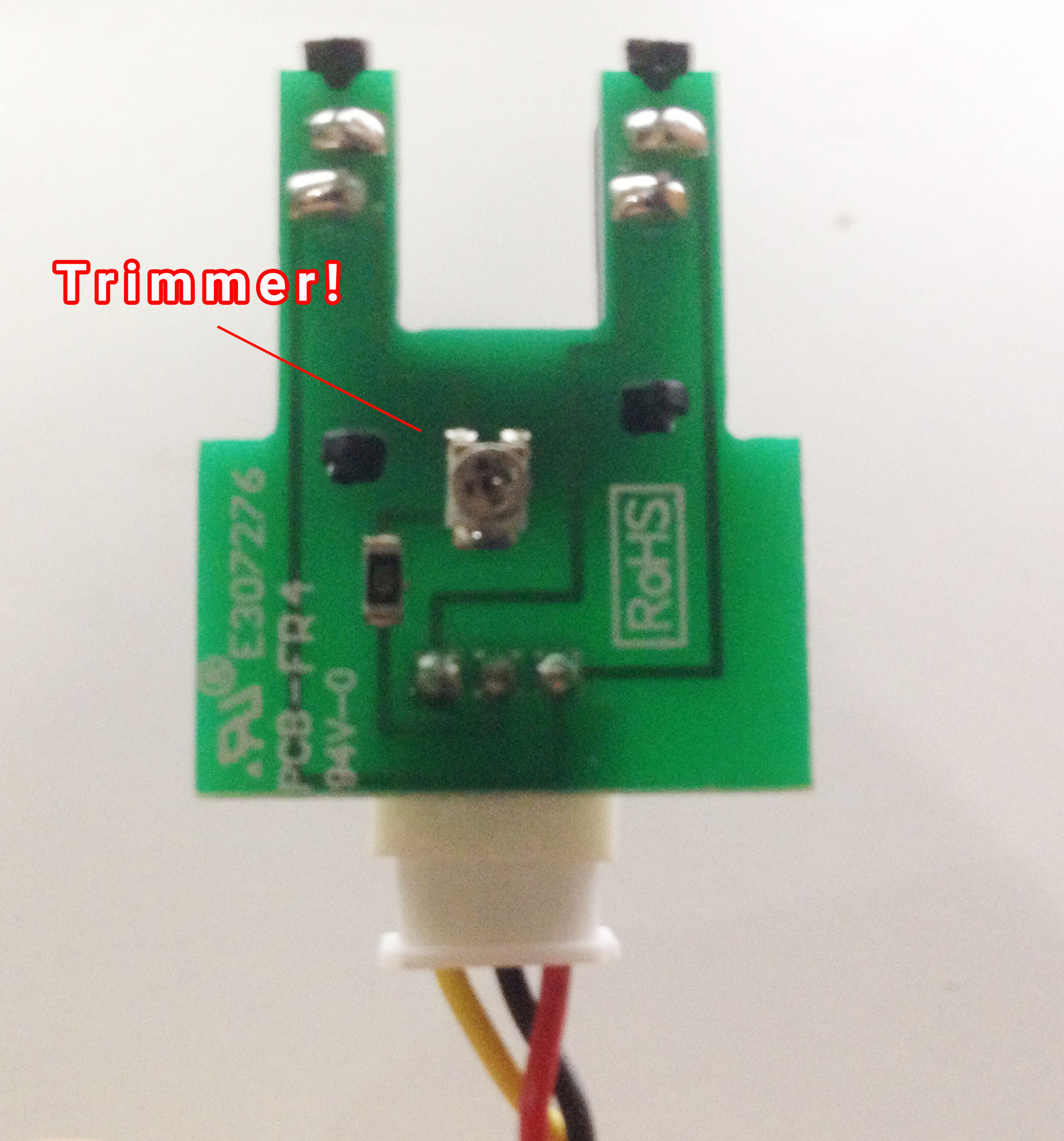
I carefully tuned the trimmer until I could get a 4.2 V output when the sensor is not submerged or is in clear water.
Now, I only needed to use the equation to provide the turbidity in NTU. Here’s the sketch:
#include <Wire.h>
#include <LiquidCrystal_I2C.h>

// Set the LCD address to 0x27 for a 16 chars and 2 line display
LiquidCrystal_I2C lcd(0x27, 16, 2);
int sensorPin = A0;
float volt;
float ntu;

void setup()
{
  Serial.begin(9600);
  lcd.begin();

  // Turn on the blacklight and print a message.
  lcd.backlight();
}

void loop()
{

    volt = 0;
    for(int i=0; i<800; i++)
    {
        volt += ((float)analogRead(sensorPin)/1023)*5;
    }
    volt = volt/800;
    volt = round_to_dp(volt,1);
    if(volt < 2.5){
      ntu = 3000;
    }else{
      ntu = -1120.4*square(volt)+5742.3*volt-4353.8;
    }
    lcd.clear();
    lcd.setCursor(0,0);
    lcd.print(volt);
    lcd.print(" V");

    lcd.setCursor(0,1);
    lcd.print(ntu);
    lcd.print(" NTU");
    delay(10);
}

float round_to_dp( float in_value, int decimal_place )
{
  float multiplier = powf( 10.0f, decimal_place );
  in_value = roundf( in_value * multiplier ) / multiplier;
  return in_value;
}
BTW, I am using an I2C LCD for this example.
[the_ad id="3059"]
The voltage from the sensor is quite noisy so I decided to take 800 samples and then average those samples:
  for(int i=0; i<800; i++)
    {
        volt += ((float)analogRead(sensorPin)/1023)*5;
    }
    volt = volt/800;
After this, I converted the voltage to NTU. But note that the equation on the graph is only true within the range of 2.5 V to 4.2 V. So I needed to set a limit. Hence:
  if(volt < 2.5){
      ntu = 3000;
    }else{
      ntu = -1120.4*square(volt)+5742.3*volt-4353.8;
    }
If the voltage reading is below 2.5 V, the NTU is set to 3000 which would be the maximum NTU value of the project.
You might noticed the difference between the original equation and the equation on my sketch (4352.9 versus 4353.8). This is because at 4.2 V, the NTU should be zero but mine gives 0.9. This could be a rounding error on the ADC’s part. I decided to filter out this 0.9 by subtracting it from the original equation. Hence the difference.
Note: the output of the sensor at clear water might sometimes diverge from the 4.2 V set value. If this happens, the on-board potentiometer (the one on the amplifier board) helps adjust it back to 4.2 V.
Video
Here’s the Arduino turbidity sensor in action:
I hope you learned something from this tutorial. Build an Arduino Turbidity Sensor project!

