

How do you measure the volume of a liquid? There are a couple or so ways to do it. One technique is to determine the level of the liquid in a container with a known cross-sectional area. For level measurements, an ultrasonic sensor is useful. Another technique is to use a water flow meter.
Introduction to Flow Meters
Flow meters come in many forms. Here are the types of flow meters common in industrial settings:
- Anemometer
- Electromagnetic
- Fluid dynamic
- Inferential
- Mass flowmeter
- Obstruction type
- Positive-displacement flow meters
- Ultrasonic
In this article, we will be using a half-effect device, an electromagnetic-type flow sensor.
Hall-effect, in general, is the presence of a transverse voltage on a current-carrying conductor with a nearby magnetic field. A voltage exists because the magnetic field tends to push or pull the charges (depending on the polarity of the magnetic field) to one side of the conductor. If one side of the conductor is more negative than the other, then a potential difference exists and thus voltage arises.
The hall-effect is best described by the video below:
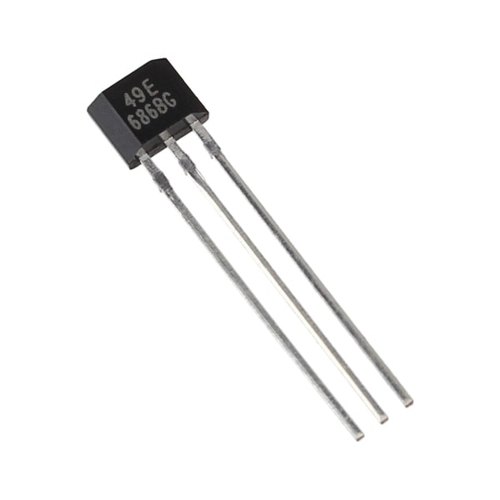
A hall-effect sensor uses this principle to detect the presence of a magnetic field. Hall-effect sensors produce a voltage that is proportional to the strength of the nearby magnetic field. These sensors look like normal transistors:
What is the role of hall-effect sensors in flow meters?
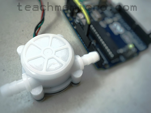
The flow meter featured in this tutorial contains a fixed-position hall-effect sensor and a magnet on one of the teeth of the turbine. As the turbine rotates with water entering, the magnet comes into close proximity to the hall-effect sensor. A series of pulses is then read from the hall-effect sensor whose frequency is analog to the rotation of the turbine.
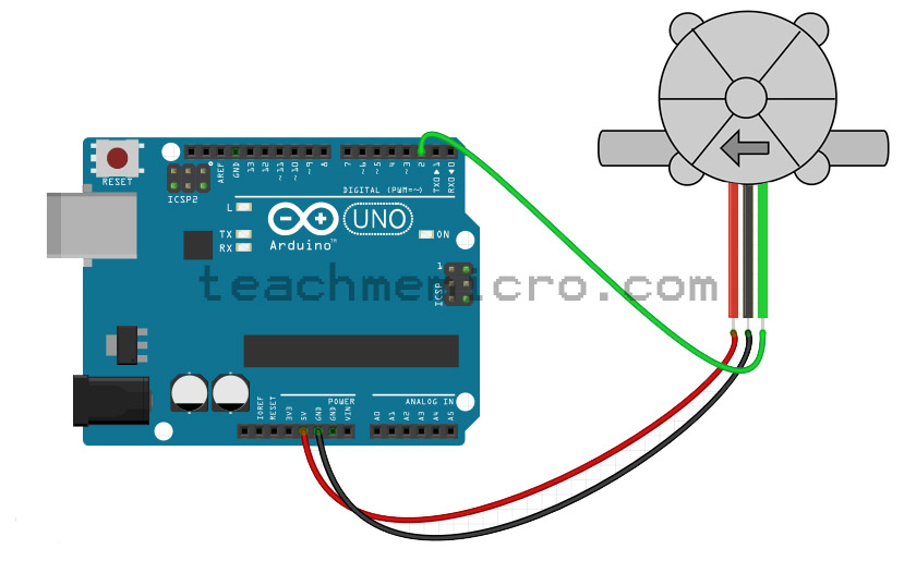
Using the Flow Sensor with Arduino
The flow sensor in this tutorial contains three pins: VCC, GND, and OUT and are colored red, black and green respectively.
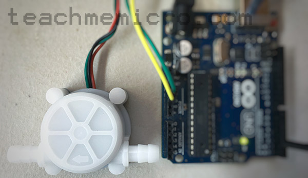
This water flow sensor needs a 6 mm hose attached to its ends. Other models have larger inlet diameters. Note that water flow sensors work best with the help of gravity. Thus, the sensor must be installed vertically so that water flows from top to bottom.
The water flow sensor pictured has the following specifications:
- Inner Diameter: 4 mm
- Outside diameter: 7 mm
- Proof Water Pressure: <0.8 MPa
- Water Flow Range: 0.3-6 L/min
- Voltage Range: 5~12 V
- Operating Current: 15 mA (DC 5V)
- Insulation Resistance: >100 MΩ
- Accuracy: ±5% (0.3-3L/min)
- The Output Pulse High Level: >4.5 VDC (DC input voltage 5 V)
- The Output Pulse Low Level: <0.5 VDC (DC input voltage 5 V)
- Output Pulse Duty Ratio: 50% ± 10%
- Water-flow Formula: 1L = 5880 square waves
- Working Humidity Range: 35% ~ 90% RH (no frost)
- Dimension: 58*35*26 mm/2.28*1.37*1.02 inches
- Weight: 30g
Notable on the list is the water flow range that this sensor can detect which is from 0.3 liters per minute to 6 liters per minute. Another important information is that 1 liter of water takes around 5880 pulses. This figure will be useful in building our Arduino water flow meter.
Since the flow sensor generates a pulse every time the magnet aligns with the hall effect sensor, we can use this pulse as an interrupt trigger. We attach the OUT pin of the water flow sensor to pin 2 of the Arduino which is interrupt pin 0.
Then, on the interrupt service routine, we sum up the pulses and divide that sum to 5880. The volume of water is now known.
volatile double waterVolume;

void setup() {
  Serial.begin(9600);  //baudrate
  waterVolume = 0;
  attachInterrupt(0, pulseHigh, RISING);  //DIGITAL Pin 2: Interrupt 0
}
void loop() {
  Serial.print("Total Water Volume:");
  Serial.print(waterVolume);
  Serial.println("   L");
  delay(500);
}

void pulseHigh()   //measure the quantity of square wave
{
  waterVolume += 1.0 / 5880.0;
}
Upload the sketch to your Arduino UNO and the volume of water is shown on the serial monitor.
Displaying Water Flow Rate
However, we also want to know the water flow rate, not just the accumulated volume of water. We know that 1 liter of water is equal to 5880 pulses. All we need to do is determine the time between pulses using the millis() function. The water flow rate would then be:
This is now the new sketch with the water flow rate:
volatile double waterVolume;
volatile double waterFlowRate = 0.0;
volatile int previousTime = 0;
boolean isTriggered = false;
double pulseWidth = 0.0;

void setup() {
  Serial.begin(9600);  //baudrate
  waterVolume = 0;
  attachInterrupt(0, pulseHigh, RISING);  //DIGITAL Pin 2: Interrupt 0
}
void loop() {
  Serial.print("Total Water Volume:");
  Serial.print(waterVolume);
  Serial.println("   L");
  Serial.print("Flow Rate:");
  if(isTriggered){
    Serial.print(waterFlowRate);
    isTriggered = false;
  }else{
    Serial.print("0.0");
  }
  Serial.println("  L/min");
  delay(500);
}

void pulseHigh()   //measure the quantity of square wave
{
  isTriggered = true;
  waterVolume += 1.0 / 5880.0;
  attachInterrupt(0, pulseLow, FALLING);
  previousTime = millis();
}

void pulseLow()
{
  pulseWidth = millis()-previousTime;
  waterFlowRate = (1000.0/5880.0) / pulseWidth;
}
Here, we acquired the time the pulse started inside the first ISR:
void pulseHigh()   //measure the quantity of square wave
{
 isTriggered = true;
 waterVolume += 1.0 / 5880.0;
 attachInterrupt(0, pulseLow, FALLING);
 previousTime = millis();
}
On the same ISR, we attached another interrupt to capture the time when the pulse ends. The second ISR:
void pulseLow()
{
 pulseWidth = millis()-previousTime;
 waterFlowRate = (1000.0/5880.0) / pulseWidth;
}
In this ISR, the pulse width is measure by subtracting the time from the previous ISR to the time in this ISR. As seen, the water flow rate is now determined.
It was necessary to add a flag (isTriggered) so that the water flow rate displayed is zero when there is no pulse coming from the flow sensor.
For questions regarding this tutorial, kindly drop a comment below!

