
How can you create sine, square or triangular waves with Arduino? Apparently, there’s a way with the help of an IC package -- the AD9833. With it, you can now create waveforms for communications, instrumentation, or other similar projects. My tutorial on building your own Arduino AD9833 signal generator after the jump.
AD9833 Waveform Generator
The AD9833, a product of Analog Devices, is a low-power, programmable waveform generator. It is capable of producing sine, square or triangular waves with frequencies from 0 to 12.5 MHz.
It’s a 10-pin IC with pinout shown below:
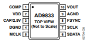
This IC has a digital oscillator that produces a representation of a waveform which then becomes an analog signal through a DAC. This circuit is also known as a direct digital synthesizer. The waveform comes out of the VOUT pin while the microcontroller interfaces with SPI pins SCLK and SDATA.
This function generator can run from a +5 V source although its internal circuitry runs on 2.5 V. The regulator that drops VDD voltage to 2.5 V requires a 100 nF external decoupling capacitor on the CAP/2.5 V pin. Moreover, the COMP pin is for decoupling the DAC bias voltage and thus also requires a 10 nF capacitor to ground.
AD9833 Operation
The AD9833 communicates with microcontrollers via SPI. It has a control register for its configuration and frequency and phase registers for specifying the frequency and phase of the output waveform.
Note that there are two channels, thus, there is one frequency and phase registers for each channel.
The frequency output formula is:
![]()
Where fMCLK is equal to the crystal frequency on MCLK pin. This output frequency then shifts to a phase given by:
![]()
FreqReg (28-bit) and PhaseReg (12-bit) are data to be written to the frequency and phase registers.
Understanding phase and frequency in waveforms.
Control and Data Bits
For the AD9833 to operate, the microcontroller sends 16-bit words in frames. The state of the FSYNC pin acts as a frame for each 16-bit word, that is, the AD9833 can only read data when FSYNC is low.
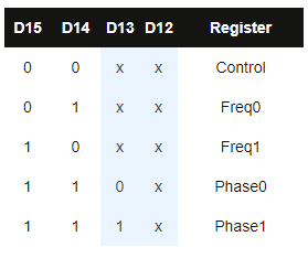
Bits 15 and 14 determine the location of the register to which the data is written. When these bits are both 0, data is sent to the control register. Otherwise, data is sent to other registers. See table below:
The rest of the bits are either data (when in frequency or phase write) or other control bits.
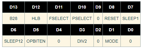
When writing to the control register, the rest of the bits are as follows:
B28 - if set, allows two successive frames as 14 MSBs and 14 LSBS.
HLB - if B28 is not set, the state of HLB determines if the received data is 14 MSB (HLB=1) or 14 LSB (HLB=0).
FSELECT - determines which channel to use for frequency
PSELECT - determines which channel to use for phase
RESET - resets internal registers but not the frequency, phase, and control registers
SLEEP1, SLEEP12

OPBITEN, DIV2, MODE

You cannot configure the AD9833 with just a single 16-bit word. A series of frames must be sent by the microcontroller to achieve the right configuration.
Example Data Transmission
Let’s have an example: a 25 MHz crystal attaches to the MCLK pin and your target is a 400 Hz sine wave at channel 0, without any phase shift. The value to be written to the frequency register is then:
![]()
The first 16-bit word to be sent is for the control register. We also want the IC to reset. Hence, the 16 bits would be:
![]()
Note that bit 13 (B28) is set because we want that successive frames to be written immediately to the frequency register. Also notice that the OPBITEN, Mode, and DIV2 bits are also zeroes, indicating that the output waveform is a sine wave.
The next word would be:
![]()
Here, bit 15 and 14 points to the Freq0 register address (channel 0). The rest of the bits is the 14 MSB of the frequency we had earlier.
The next word:
![]()
Still, bits 15 and 14 points to Freq0, and the rest of the bits are the 14 LSB of the frequency, which is now all zeroes.
Next, we write to the phase register, even though it’s zero in this case:
![]()
Here, bits 15 and 14 point to Phase0.
Finally, we have:
![]()
This writes to control register and issue a reset. A signal then appears at the output after seven MCLK cycles.
Using the AD9833 with Arduino
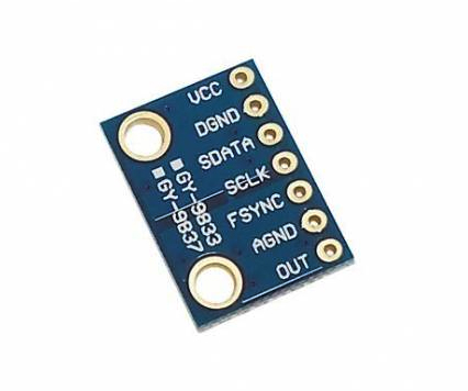
AD9833 Module
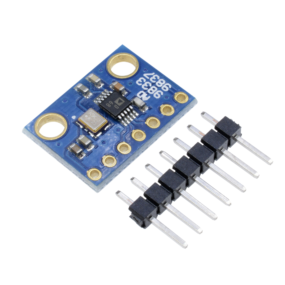
To use the AD9833 with an Arduino, it’s better to buy a breakout board like this:
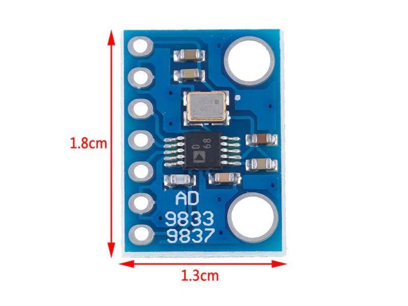
Besides giving direct access to the AD9833 interface pins, this already has a crystal oscillator of 25 MHz and all the needed capacitors.
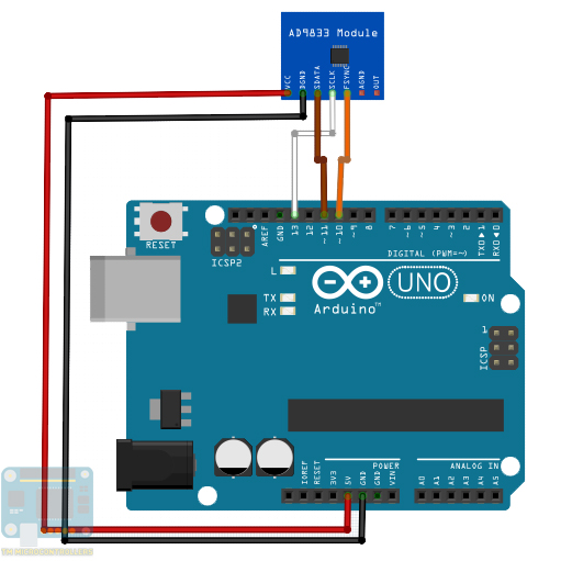
Example Arduino Sketch
The library I recommend is that by Bill Williams. It uses the Arduino’s hardware SPI and so the breakout board connects to Arduino like this:
The library has convenient functions for us to go away from all those bits and bytes. For example, producing a 1000 Hz sine wave only requires this code:
#include <AD9833.h>     // Include the library

#define FNC_PIN 10       // Can be any digital IO pin

AD9833 gen(FNC_PIN);       // Defaults to 25MHz internal reference frequency

void setup() {
    gen.Begin();
    gen.ApplySignal(TRIANGLE_WAVE,REG0,1000);
    gen.EnableOutput(true);
}

void loop() {
}
Here, the object initiates with:
AD9833 gen(FNC_PIN);
The FNC_PIN is assignable to any pin. Here, the FNC_PIN connects to digital pin 10. The rest of the pins, however, must connect to the default Arduino SPI pins.
The first command after declaring the object must be this:
gen.Begin();
Then the function for specifying the type of waveform, channel, and frequency follow:
gen.ApplySignal(SINE_WAVE,REG0,1000);
The type of waveform can be any of these:
SINE_WAVE
TRIANGLE_WAVE
SQUARE_WAVE
HALF_SQUARE_WAVE
Also recall that there are only two channels, so the channel parameter can only be REG0 or REG1.
Finally, the frequency can be any float value from 0 to 12500000.
BTW, this function defaults to phase register 0 and phase value = 0. If you want to change the phase to 12.5 radians (relative to another channel), modify the function call as:
gen.ApplySignal(SINE_WAVE,REG0,1000,REG0,12.5);
For those with Arduino 1.6.6 and above, you can use the serial plotter to view the waveforms from AD9833. Just connect the VOUT pin to Arduino’s A0 pin and modify the sketch like this:
#include <AD9833.h>     // Include the library

#define FNC_PIN 10       // Can be any digital IO pin

AD9833 gen(FNC_PIN);       // Defaults to 25MHz internal reference frequency

void setup() {
    gen.Begin();
    gen.ApplySignal(TRIANGLE_WAVE,REG0,1000);
    gen.EnableOutput(true);
    Serial.begin(250000);
}

void loop() {
  Serial.println(analogRead(A0));
}
Note however that the Arduino’s ADC can sample only up to 9615 Hz. Hence, signals above this may not show correctly. Also, there are no sweep adjustments like in oscilloscopes so faster frequencies might not look right.
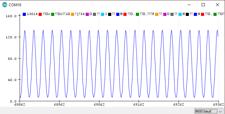
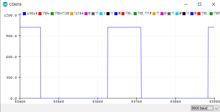
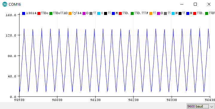
Example Outputs
With the VOUT pin of the AD9833 to A0 pin of Arduino, we can view the waveforms from the device.
Here’s a 10 Hz sine wave:
A 1 Hz square wave:
Finally, a 10 Hz triangular wave:
I hope this tutorial has helped you create your own Arduino signal generator. For comments, questions, or suggestions, kindly drop a comment below!

