
One of the most important things your microcontroller can do is read analog voltages. It is important particularly in interfacing with sensors where most throw varying voltage levels that represent varying physical quantities (temperature, pressure, etc.). Microcontrollers, including the Beaglebone Black, have analog to digital converters to do this. Here I will show you how to use the Beaglebone Black ADC module.
If this is your first time reading my site, you must know that:
My BBB runs on Ubuntu 16.04 LTS with kernel 4.4.9-ti-r25. There is a slight difference on this distro and with others. The differences will be included in this tutorial
Some ADC Math
The BBB has a 12-bit ADC module with a 1.8 V reference. The AM335x, which is the BBB's CPU, uses successive approximation and can take 200,000 samples per second. The digital value can be calculated using the formula:
This means the Beaglebone Black can read voltage levels from 439.6 uV to 1.8 V. If your sensor goes above 1.8, then you need additional circuits to scale down the voltage.
The Device Tree
The Beaglebone Black ADC function is not enabled by default. You need this device tree to enable it:
/*
 * Copyright (C) 2012 Texas Instruments Incorporated - http://www.ti.com/
 *
 * This program is free software; you can redistribute it and/or modify
 * it under the terms of the GNU General Public License version 2 as
 * published by the Free Software Foundation.
 */
/dts-v1/;
/plugin/;

/ {
	compatible = "ti,beaglebone", "ti,beaglebone-black", "ti,beaglebone-green";

	// identification
	part-number = "BB-ADC";
	version = "00A0";

	// resources this cape uses
	exclusive-use =
		"P9.39",		// AIN0
		"P9.40",		// AIN1
		"P9.37",		// AIN2
		"P9.38",		// AIN3
		"P9.33",		// AIN4
		"P9.36",		// AIN5
		"P9.35",		// AIN6

		"tscadc";	// hardware ip used


	fragment@0 {
		target = <&tscadc>;
		__overlay__ {

			status = "okay";
			adc {
				ti,adc-channels = <0 1 2 3 4 5 6>;
				ti,chan-step-avg = <0x16 0x16 0x16 0x16 0x16 0x16 0x16>;
				ti,chan-step-opendelay = <0x98 0x98 0x98 0x98 0x98 0x98 0x98>;
				ti,chan-step-sampledelay = <0x0 0x0 0x0 0x0 0x0 0x0 0x0>;
			};
		};
	};
};
As you can see above, the pins P9.39, P9.40, P9.37, P9.38, P9.33, P9.36, P9.35 are your analog input pins. Compile the above .dts file to a .dtbo binary object:
dtc -O dtb -o BB-ADC-00A0.dtbo -b 0 -@ BB-ADC-00A0.dts
The compiled .dtbo object must then be moved to /lib/firmware:
mv BB-ADC-00A0.dtbo /lib/firmware
Both the .dts and .dtbo files are already in the /lib/firmware in the latest debian and angstrom distro.
The next step is to load the device tree fragment into the cape manager using:
echo BB-ADC > /sys/devices/platform/bone_capemgr/slots
For debian and ubuntu, the slots location is:
/sys/devices/bone_capemgr.8/slots
You can check if it's loaded by doing:
root@arm:~# cat /sys/devices/platform/bone_capemgr/slots
 0: PF----  -1
 1: PF----  -1
 2: PF----  -1
 3: PF----  -1
 4: P-O-L-   0 Override Board Name,00A0,Override Manuf,BB-ADC
I don't have any other device tree overlay loaded so it's the only thing you can see.
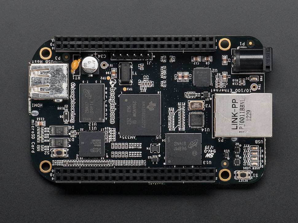
Shameless plug but you have to grab this board. It's very much like the Beaglebone Black only smaller:
If the above steps are successful then the /sys/bus/iio/devices folder will now have been created.
root@arm:/sys/bus/iio/devices# cd iio:device0
root@arm:/sys/bus/iio/devices/iio:device0# ls
buffer  in_voltage0_raw  in_voltage2_raw  in_voltage4_raw  in_voltage6_raw  of_node  scan_elements  uevent
dev     in_voltage1_raw  in_voltage3_raw  in_voltage5_raw  name             power    subsystem
root@arm:/sys/bus/iio/devices/iio:device0#
The five analog channels (AIN0 to AIN5) are represented by the in_voltagex_raw files you see above. To read the input on a particular channel, just do:
root@arm:/sys/bus/iio/devices/iio:device0# cat in_voltage0_raw
3914
I didn't connect anything so mine reads 3914 (which I believe is due to noise voltages).
Beaglebone Black ADC Continuous Reading
So far we are reading analog voltages in one-shot mode. Most applications need continuous reading of input values. For continuous mode, we need a buffer to capture the input values while the BBB is doing something else. The buffer can be enabled by doing:
root@arm:~# echo 1 > /sys/bus/iio/devices/iio\:device0/scan_elements/in_voltage0_en
root@arm:~# echo 100 > /sys/bus/iio/devices/iio\:device0/buffer/length
root@arm:~# echo 1 > /sys/bus/iio/devices/iio\:device0/buffer/enable
The first line tells which analog channel to scan. Just change the x in in_voltagex_en if you need a different analog channel. The second line specifies the length of the buffer and the last line enables the buffer.
The kernel source has a sample application located at drivers/staging/iio/Documentation/ named generic_buffer.c. If you're like me who's lazy to download the kernel source, here's the generic_buffer.c file.
Open the nano file editor
nano generic_buffer.c
And copy-paste the code above.
However, this code uses a hardware trigger to fire up continuous ADC. You need the patch file to disable the hardware trigger.
Again, open the nano editor
nano generic_buffer.patch
and copy-paste the above code.
Run the patch command using
patch < generic_buffer.patch
You'll also need the iio_utils.c file and the iio_utils.h file and must be saved to the same directory as the generic_buffer.c file. Compile all the files using:
gcc --static generic_buffer.c iio_utils.c -o generic_buffer
Now we have an executable command to print the analog values! To use the file, just type:
root@arm:~# ./generic_buffer -n TI-am335x-adc -l 5 -c 3
Where 5 is the buffer length and 3 is the number of iterations. The above command will print 5 readings three times:
root@arm:~# ./generic_buffer -n TI-am335x-adc -l 5 -c 3
iio device number being used is 0
/sys/bus/iio/devices/iio:device0
3921.000000
3909.000000
3897.000000
3888.000000
3881.000000
3873.000000
3866.000000
3863.000000
3123.000000
3125.000000
3126.000000
3124.000000
3124.000000
3111.000000
3110.000000
If you need to go back to one-shot mode then just do:
echo 0 > /sys/bus/iio/devices/iio\:device0/buffer/enable
That's all to it. Next, I'm planning to use the analog readings and put them into a web page hosted by the BBB. Come back to this site for updates!

