
The first thing I did when I had my Beaglebone Black (BBB) was toy with it using C++. The "hello world" of embedded programming is LED blinking so that's what I did. Note that the BBB has user-accessible on-board LEDs and controlling them is very similar to the method outlined here. What I did is create a Beaglebone Black blink LED program in C++ using a LED externally connected to one of the BBB's pins. To know how to control the on-board LEDs, read the tutorial here.
There are a number of ways to control the Beaglebone Black's general input/output pins (GPIO). One way is by using Node.JS as covered on my bonescript tutorial. This tutorial will cover the sysfs method of exporting information provide by the Beaglebone Black's device tree. If you are new to Linux command-line environment, read this first.
Note that this tutorial presumes you have Ubuntu 16.04 with kernel 4.49 installed. Go here to know how to install Ubuntu to your BBB.
Sysfs
Sysfs is a virtual file system provided by the Linux kernel that exports information and gives access to devices and drivers of the Beaglebone Black. The information is from the device tree, which is a neat data structure that makes it easier to access the hardware. The device tree is well explained here.
Sysfs is mounted on the /sys/ folder. It's very helpful to be a root user first so your first command should be sudo su.
Here's what my /sys/ folder looks like (Ubuntu):
root@arm: cd /sys/
root@arm: /sys# ls
block bus class dev devices firmware fs kernel module power
There are a lot of things here but we'll ignore them for this tutorial. The GPIO of the BBB is under the /class/gpio folder:
root@arm: /sys/class/gpio# ls
export gpiochip0 gpiochip32 gpiochip64 gpiochip96 unexport
The gpiochip# you see are the GPIO controllers with the # indicating the start of the GPIO number under them. This means, for example, that GPIO_32 to GPIO_63 is controlled by gpiochip32.
Schematic Diagram
I wired a LED (with a 470 ohm resistor in series) to pin #13 on the P9 header. The choice of resistor is based on the maximum current output of the BBB's GPIO pins which is around 6 to 7 mA (3.3/470 ≈ 7 mA).
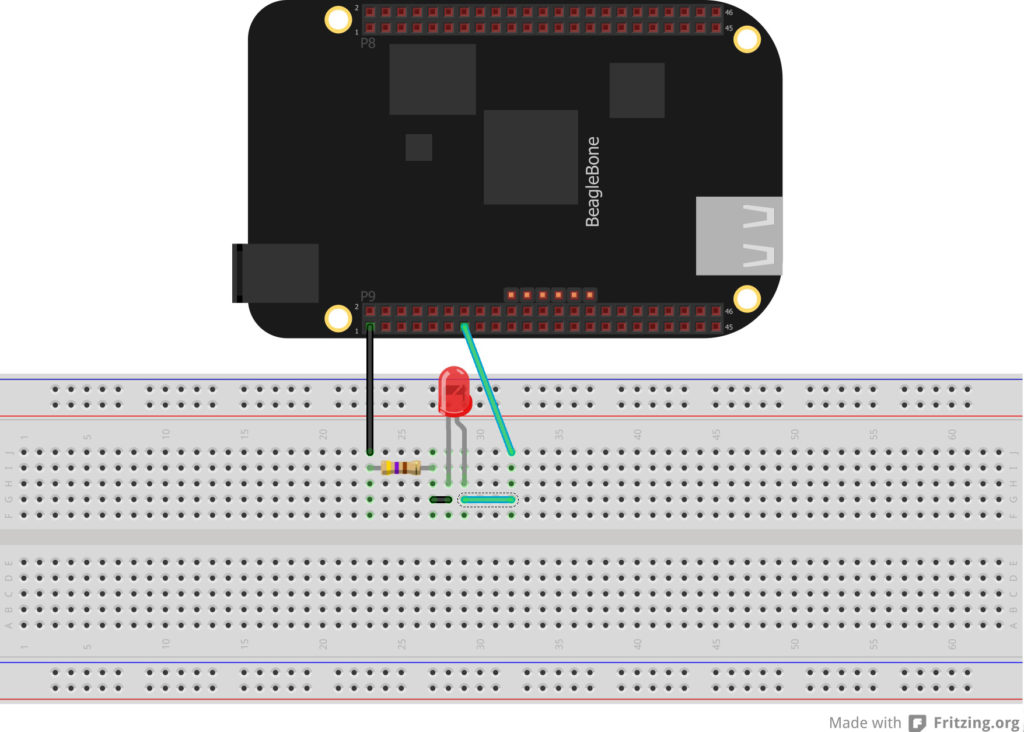
Pin 13 on P9 is GPIO_23. To be able to control this pin, we need to export from the device tree:
root@arm:/sys/class/gpio# echo 23 > export
root@arm:/sys/class/gpio# ls
export gpio23 gpiochip0 gpiochip32 gpiochip64 gpiochip96 unexport
You will see that gpio23 is now part of the gpio folder. List the parameters of gpio23 using ls
root@arm:/sys/class/gpio/gpio23# ls
active_low device direction edge power subsystem uevent value
We are interested in making GPIO_23 as output. This is done by echoing "out" to the "direction" parameter.
root@arm:/sys/class/gpio/gpio23# echo out > direction
root@arm:/sys/class/gpio/gpio23# cat direction out
We can now set GPIO_23 high or low by echoing "1" or "0" to the "value" parameter.
root@arm:/sys/class/gpio/gpio23# echo 1 > value
root@arm:/sys/class/gpio/gpio23# echo 0 > value
The Complete Code
Now all we need to go is to combine all the steps we've done in a single c++ file.
C++ File:
#include <unistd.h>
#include <stdio.h>

using namespace std;

int main() {
  FILE *export_file = NULL; //declare pointers
  FILE *IO_direction = NULL;
  FILE *IO_value = NULL;
  char str1[] = "0";
  char str2[] = "1";
  char str3[] = "out";
  char str[] = "23";
  //this part here exports gpio23
  export_file = fopen ("/sys/class/gpio/export", "w");
  fwrite (str, 1, sizeof(str), export_file);
  fclose (export_file);
  //this part here sets the direction of the pin
  IO_direction = fopen("/sys/class/gpio/gpio23/direction", "w");
  fwrite(str3, 1, sizeof(str3), IO_direction);
  //set the pin to HIGH
  fclose(IO_direc1tion);
  usleep (1000000);
  for (int i=0; i<10; i++)
  {
     //blink LED 10 times
     IO_value = fopen ("/sys/class/gpio/gpio23/value", "w");
     fwrite (str2, 1, sizeof(str2), IO_value);
     //set the pin to HIGH fclose (IO_value);
     usleep (1000000);
     //delay for a second
     IO_value = fopen ("/sys/class/gpio/gpio23/value", "w");
     fwrite (str1, 1, sizeof(str1), IO_value);
     //set the pin to LOW
     fclose (IO_value);
     usleep (1000000);
     //delay for a second
  }
}
Load the Code Using Nano:
Put this code to your BBB by typing (on root):
root@arm:~# nano blink.cppThis will open the Nano text editor. Paste the code above (right-click if you're on putty) and press ctrl+x. Choose Y to save the file then enter. To compile the code, type:
root@arm:~# g++ blink.cpp -o blinkThis will create a executable file named blink. To execute it, type:
root@arm:~ ./blinkThe LED will now blink ten times with one second intervals.
While the method presented here is simple, there is one tradeoff: you can't use the pin directly for other things like USART, PWM, etc. The device tree overlay method is much more powerful but is a little bit complex. I will cover that in the next tutorial so stay tuned!

