
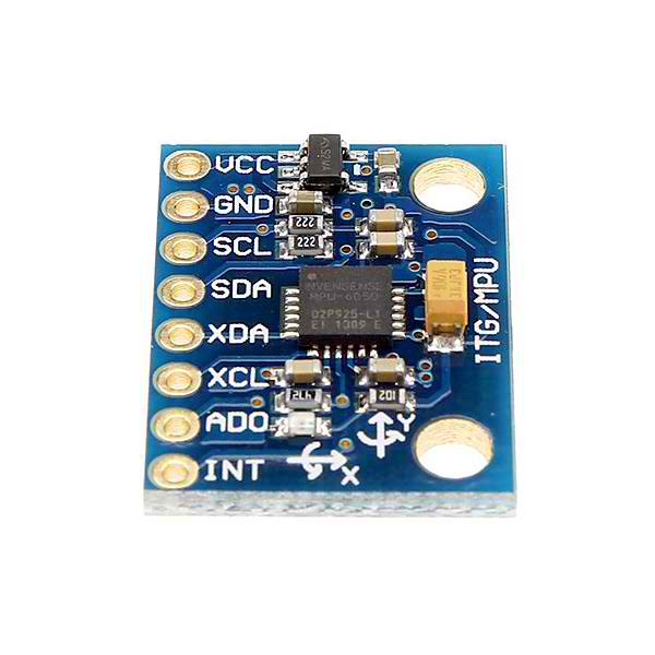
We covered the Beaglebone Black I2C basics in our last tutorial. This time, we'll try to communicate with a device through the I2C protocol. This device, the MPU6050, is a gyroscope + accelerometer integrated circuit that is very popular among makers and enthusiasts.
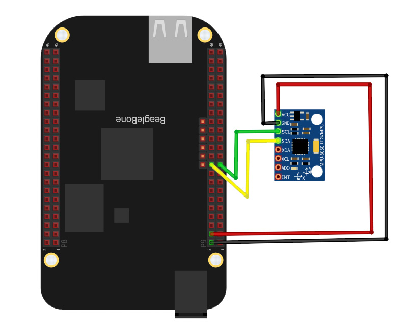
Beaglebone Black MPU6050 Wiring Diagram
First thing you need to do, of course, is connect the MPU6050 to the Beaglebone Black. We will be using I2C-2 bus of the BBB (as per the previous tutorial) and so our SDA pin will be P9_20 while our SCL pin will be P9_19. Also, connect the MPU6050 VCC pin to the P9_4 (3.3 V VDD) and its ground pin to P9_2 (DGND). Here's the fritzing diagram:
You can check if your connections are correct using the command i2cdetect -r 2:
root@arm:~/i2c-tut# i2cdetect -r 2
WARNING! This program can confuse your I2C bus, cause data loss and worse!
I will probe file /dev/i2c-2 using read byte commands.
I will probe address range 0x03-0x77.
Continue? [Y/n] y
     0  1  2  3  4  5  6  7  8  9  a  b  c  d  e  f
00:          -- -- -- -- -- -- -- -- -- -- -- -- --
10: -- -- -- -- -- -- -- -- -- -- -- -- -- -- -- --
20: -- -- -- -- -- -- -- -- -- -- -- -- -- -- -- --
30: -- -- -- -- -- -- -- -- -- -- -- -- -- -- -- --
40: -- -- -- -- -- -- -- -- -- -- -- -- -- -- -- --
50: -- -- -- -- UU UU UU UU -- -- -- -- -- -- -- --
60: -- -- -- -- -- -- -- -- 68 -- -- -- -- -- -- --
70: -- -- -- -- -- -- -- --
root@arm:~/i2c-tut#
You'll see that address 68 is filled out. That's the MPU6050!
The MPU6050 Registers
Accelerometer and Gyroscope
The MPU6050 has registers from 0x0D to 0x75. Each of these registers are 8-bits wide and have specific functions. To see all of these registers, download the MPU6050 register map.
For the purpose of this tutorial, we'll be reading from the accelerometer and gyroscope registers. The accelerometer and gyroscope data are 16 bits wide and so data from each axis uses two registers. Here's what I'm talking about:
| Register | Address |
|---|---|
| ACCEL_XOUT_H | 0x3B |
| ACCEL_XOUT_L | 0x3C |
| ACCEL_YOUT_H | 0x3D |
| ACCEL_YOUT_L | 0x3E |
| ACCEL_ZOUT_H | 0x3F |
| ACCEL_ZOUT_L | 0x40 |
| GYRO_XOUT_H | 0x43 |
| GYRO_XOUT_L | 0x44 |
| GYRO_YOUT_H | 0x45 |
| GYRO_YOUT_L | 0x46 |
| GYRO_ZOUT_H | 0x47 |
| GYRO_ZOUT_L | 0x48 |
We can check out the contents of these registers through i2cdump:
root@arm:~/i2c-tut# i2cdump 2 0x68
No size specified (using byte-data access)
WARNING! This program can confuse your I2C bus, cause data loss and worse!
I will probe file /dev/i2c-2, address 0x68, mode byte
Continue? [Y/n] y
     0  1  2  3  4  5  6  7  8  9  a  b  c  d  e  f    0123456789abcdef
00: ff 01 ff 2d af 0f 05 90 fb 0b 05 44 28 70 6e 94    .?.-???????D(pn?
10: c6 00 00 00 00 00 00 00 00 00 00 00 00 00 00 00    ?...............
20: 00 00 00 00 00 00 00 00 00 00 00 00 00 00 00 00    ................
30: 00 00 00 00 00 00 00 00 00 00 00 00 00 00 00 00    ................
40: 00 00 00 00 00 00 00 00 00 00 00 00 00 00 00 00    ................
50: 00 00 00 00 00 00 00 00 00 00 00 00 00 00 00 00    ................
60: 00 00 00 00 00 00 00 00 00 00 00 40 00 00 00 00    ...........@....
70: 00 00 00 00 00 68 00 00 00 00 00 00 00 00 00 00    .....h..........
80: ff 01 ff 2d af 0f 05 90 fb 0b 05 44 28 70 6e 94    .?.-???????D(pn?
90: c6 00 00 00 00 00 00 00 00 00 00 00 00 00 00 00    ?...............
a0: 00 00 00 00 00 00 00 00 00 00 00 00 00 00 00 00    ................
b0: 00 00 00 00 00 00 00 00 00 00 00 00 00 00 00 00    ................
c0: 00 00 00 00 00 00 00 00 00 00 00 00 00 00 00 00    ................
d0: 00 00 00 00 00 00 00 00 00 00 00 00 00 00 00 00    ................
e0: 00 00 00 00 00 00 00 00 00 00 00 40 00 00 00 00    ...........@....
f0: 00 00 00 00 00 68 00 00 00 00 00 00 00 00 00 00    .....h..........
Here you'll see that the registers on the table above have zero values. This is because we need to wake the MPU6050 up before it gives data.
How to Wake Up the MPU6050
To wake up the MPU6050, we need to write zero to the PWR_MGMT_1 register which is at address 0x6B. Here's how to do that:
root@arm:~/i2c-tut# i2cset 2 0x68 0x6B 0
WARNING! This program can confuse your I2C bus, cause data loss and worse!
I will write to device file /dev/i2c-2, chip address 0x68, data address
0x6b, data 0x00, mode byte.
Continue? [Y/n] y
After that, we can use i2cdump again to check.
root@arm:~/i2c-tut# i2cdump 2 0x68
No size specified (using byte-data access)
WARNING! This program can confuse your I2C bus, cause data loss and worse!
I will probe file /dev/i2c-2, address 0x68, mode byte
Continue? [Y/n] y
     0  1  2  3  4  5  6  7  8  9  a  b  c  d  e  f    0123456789abcdef
00: ff 01 ff 2d af 0f 05 90 fb 0b 05 44 28 70 6e 94    .?.-???????D(pn?
10: c6 00 00 00 00 00 00 00 00 00 00 00 00 00 00 00    ?...............
20: 00 00 00 00 00 00 00 00 00 00 00 00 00 00 00 00    ................
30: 00 00 00 00 00 00 00 00 00 00 01 2e 28 07 e4 d3    ..........?.(???
40: b4 f3 d0 ff e7 01 ec 00 68 00 00 00 00 00 00 00    ???.???.h.......
50: 00 00 00 00 00 00 00 00 00 00 00 00 00 00 00 00    ................
60: 00 00 00 00 00 00 00 00 00 00 00 00 00 00 00 25    ...............%
70: 00 00 00 00 00 68 00 00 00 00 00 00 00 00 00 00    .....h..........
80: ff 01 ff 2d af 0f 05 90 fb 0b 05 44 28 70 6e 94    .?.-???????D(pn?
90: c6 00 00 00 00 00 00 00 00 00 00 00 00 00 00 00    ?...............
a0: 00 00 00 00 00 00 00 00 00 00 00 00 00 00 00 00    ................
b0: 00 00 00 00 00 00 00 00 00 00 01 2e 34 07 04 d2    ..........?.4???
c0: 94 f3 d0 ff 98 01 b2 00 4e 00 00 00 00 00 00 00    ???.???.N.......
d0: 00 00 00 00 00 00 00 00 00 00 00 00 00 00 00 00    ................
e0: 00 00 00 00 00 00 00 00 00 00 00 00 00 00 03 fd    ..............??
f0: 00 00 00 00 00 68 00 00 00 00 00 00 00 00 00 00    .....h..........
The accelerometer and gyroscope registers now have values!
Try reorienting the MPU6050 and do the i2cdump again. You should have different values on the accelerometer and gyroscope registers.
Getting Individual Values
To get an individual register value, we can use the i2cget command. For example, I'll read the value of ACCEL_XOUT_H register (address 0x3B):
root@arm:~/i2c-tut# i2cget 2 0x68 0x3B
WARNING! This program can confuse your I2C bus, cause data loss and worse!
I will read from device file /dev/i2c-2, chip address 0x68, data address
0x3b, using read byte data.
Continue? [Y/n] y
0x30
The output 0x30 is the high byte of the MPU6050's acceleration in the x-axis. To get the low byte simply change the address:
root@arm:~/i2c-tut# i2cget 2 0x68 0x3C
WARNING! This program can confuse your I2C bus, cause data loss and worse!
I will read from device file /dev/i2c-2, chip address 0x68, data address
0x3c, using read byte data.
Continue? [Y/n] y
0xf8
The low byte is 0xf8. This means the acceleration in the x-axis is 0x30f8 or 12, 536 in decimals.
Scaling the MPU6050 Raw Data
What we've read from the MPU6050 so far is raw data and needs to be converted to make sense. The acceleration data is measured in g (acceleration due to gravity) units while the gyroscope data is measured in degrees per second. The MPU6050 uses 2g and 250 deg/sec as default sensitivities.
Since each axes is 16 bytes and is signed, the raw values will range from -32,768 to 32, 767. This means acceleration in axes X ,Y and Z should have values within these ranges that represent the effect of gravity. For the default sensitivity which is 2g, the scaling factor should be around 16, 384 (32, 768/2).
In the same way, the X, Y and Z gyro data should have raw data readings from +250 to -250. According to the datasheet, the best scaling factor to use is 131.
However, even with scaling factors you may not get the exact acceleration and rotational speed since there will always be noise and sensor reading errors.
C++ Code
Following the discussion above, we can now write a C++ code that displays the accelerometer and gyroscope values:
/BBB-MPU6050.cpp
by OP from teachmemicro.com
*/

#include <cstdlib>
#include <cstdio>
#include <iostream>
#include <stdexcept>
#include <cstring>
#include <string>
#include <memory>
#include <array>

using namespace std;

int16_t accel_x;
int16_t accel_y;
int16_t accel_z;
int16_t gyro_x;
int16_t gyro_y;
int16_t gyro_z;

const char* deviceADDR = " 0x68";
const char* PWR_MGMT_1 = " 0x6B";
const char* ACCEL_X_OUT_H = " 0x3B ";
const char* ACCEL_X_OUT_L = " 0x3C ";
const char* ACCEL_Y_OUT_H = " 0x3D ";
const char* ACCEL_Y_OUT_L = " 0x3E ";
const char* ACCEL_Z_OUT_H = " 0x3F ";
const char* ACCEL_Z_OUT_L = " 0x40 ";
const char* GYRO_X_OUT_H = " 0x43 ";
const char* GYRO_X_OUT_L = " 0x44 ";
const char* GYRO_Y_OUT_H = " 0x45 ";
const char* GYRO_Y_OUT_L = " 0x46 ";
const char* GYRO_Z_OUT_H = " 0x47 ";
const char* GYRO_Z_OUT_L = " 0x48 ";

const char* cmdGet = "i2cget -y 2";
const char* cmdSet = "i2cset -y 2";

/*exec function that runs bash commands in c++
string exec(char* cmd) {
	string data;
	FILE * stream;
	const int max_buffer = 256;
	char buffer[max_buffer];
	strcat(cmd," 2>&1");
	stream = popen(cmd, "r");

	if (stream) {
		while (!feof(stream))
			if (fgets(buffer, max_buffer, stream) != NULL) data.append(buffer);
			pclose(stream);
		}
	return data;
}

/*function that performs geti2c
string get(const char* reg1, const char* reg2){
	char str[100];
	string str2;

	strcpy(str, cmdGet);
	strcat(str, reg1);
	strcat(str, reg2);

	str2 = exec(str);
	return str2;
}

/*function that performs seti2c
void set(const char* reg1, const char* reg2, int value){
	char str[100];
	string str2;

	strcpy(str, cmdSet);
	strcat(str, reg1);
	strcat(str, reg2);
	strcat(str, to_string(value).c_str());

	str2 = exec(str);
}

int main(){
	set(deviceADDR, PWR_MGMT_1, 0);	//turn on the MPU6050
	while(true){
		accel_x = stoi(get(deviceADDR, ACCEL_X_OUT_H), nullptr, 16) << 8 + stoi(get(deviceADDR, ACCEL_X_OUT_L), nullptr, 16);
		accel_y = stoi(get(deviceADDR, ACCEL_Y_OUT_H), nullptr, 16) << 8 + stoi(get(deviceADDR, ACCEL_Y_OUT_L), nullptr, 16);
		accel_z = stoi(get(deviceADDR, ACCEL_Z_OUT_H), nullptr, 16) << 8 + stoi(get(deviceADDR, ACCEL_Z_OUT_L), nullptr, 16);
		accel_x = accel_x / 16384;
		accel_y = accel_y / 16384;
		accel_z = accel_z / 16384;

		gyro_x = stoi(get(deviceADDR, GYRO_X_OUT_H), nullptr, 16) << 8 + stoi(get(deviceADDR, GYRO_X_OUT_L), nullptr, 16);
		gyro_y = stoi(get(deviceADDR, GYRO_Y_OUT_H), nullptr, 16) << 8 + stoi(get(deviceADDR, GYRO_Y_OUT_L), nullptr, 16);
		gyro_z = stoi(get(deviceADDR, GYRO_Z_OUT_H), nullptr, 16) << 8 + stoi(get(deviceADDR, GYRO_Z_OUT_L), nullptr, 16);
		gyro_x = gyro_x / 131;
		gyro_y = gyro_y / 131;
		gyro_z = gyro_z / 131;

		cout << "X-acc: " << accel_x << " Y-acc: " << accel_y << " Z-acc: " << accel_z << endl;
		cout << "X-gyro: " << gyro_x << " Y-gyro: " << gyro_y << " Z-gyro: " << gyro_z << endl;

	}
	return 0;
}
You can now use your MPU6050 to create motion-based apps for the Beaglebone Black!
If you find this post useful, kindly post a comment below. Come back to this site for more updates!

