
Now we'll use the Beaglebone Black PWM to control a servo motor. PWM, which is short for pulse width modulation, is widely used for controlling motors (dc and servomotors). PWM is also used in controlling power delivered to a load or device without using "power-eating" rheostat.
Beaglebone Black PWM on Ubuntu
While there are a lot of tutorials out there about using the BBB's PWM module, this tutorial is slightly different since I am using Ubuntu 16.04 LTS with kernel 4.4.9. There are a few changes in the way you can use the PWM using this kernel as compared to earlier ones like 3.8, etc. If you're not sure which version you are using, type cat /etc/issue for the distro name and version and uname -r for the kernel version in your BBB's ssh terminal. This is what mine looks like:
olan@arm:~$ cat /etc/issue
Ubuntu 16.04 LTS
\n \l rcn-ee.net console Ubuntu Image 2016-05-12
Support/FAQ: http://elinux.org/BeagleBoardUbuntu
default username:password is [ubuntu:temppwd]
The IP Address for usb0 is: 192.168.7.2
olan@arm:~$ uname -r
4.4.9-ti-r2
Instructions on how to get Ubuntu to your BBB is found here.
You also need to know what device tree overlays are before pushing through this tutorial. Basically, a device tree is a way to access the hardware components of a device such as a BBB. A device tree overlay is a file that we can use to modify the hardware without recompiling the device's kernel. I would suggest you read this tutorial by Adafruit if to get you acquainted with device tree overlays.
If you are not using Ubuntu or if you find this tutorial too advanced, you can still use PWM using bonescript.
Installing the Device Tree Overlay
Preliminaries
First, login as root user so that you wouldn't need to use sudo on all commands (you'd have to enter your user password):
olan@arm:~$ sudo su
[sudo] password for olan:
root@arm:/home/olan#
Next is to install the device tree overlay. I have scourged the web looking for the correct device tree overlay for my device and my kernel version. The one that worked for me can be found here: https://github.com/beagleboard/bb.org-overlays/tree/master/src/arm. You can clone this repository to your BBB.
root@arm:/home/olan# git clone https://github.com/beagleboard/bb.org-overlays/tree/master/src/armThe repository has three pwm device tree overlays. The one that you'll be using depends on which pwm output you will use. The BBB has six pwm outputs spread out to 12 pins (two pins per pwm output):
| PWM Module | Pin |
| EHRPWM0A | P9_22, P9_31 |
| EHRPWM0B | P9_21, P9_29 |
| EHRPWM1A | P9_14, P8_36 |
| EHRPWM1B | P9_16, P8_34 |
| EHRPWM2A | P8_19, P8_45 |
| EHRPWM2B | P8_13, P8_46 |
For this tutorial, I'll be using EHRPWM1A at pin P9_14. That means I'll be using the device tree overlay BB-PWM1-00A0.dts. Here is its contents:
/*
* Copyright (C) 2016 Seeed Studio.
*
* This program is free software; you can redistribute it and/or modify
* it under the terms of the GNU General Public License version 2 as
* published by the Free Software Foundation.
*/
/dts-v1/;
/plugin/;
/{
compatible = "ti,beaglebone", "ti,beaglebone-black", "ti,beaglebone-green";
part-number = "BB-PWM1";
version = "00A0";

fragment@0 {
target = <&am33xx_pinmux>;
       __overlay__ {
              pinctrl_spec: Panel_Pins {
                 pinctrl-single,pins = < 0x48 0x06 /* (U14) gpmc_a2.ehrpwm1A */ 0x4c 0x06 /* (T14) gpmc_a3.ehrpwm1B */ >;
              };
       };
};
fragment@1 {
target = <&ocp>;
       __overlay__ {
              test_helper: helper {
                   compatible = "bone-pinmux-helper";
                   pinctrl-names = "default";
                   pinctrl-0 = <pinctrl_spec>;
                   status = "okay";
              };
       };
};
fragment@2 {
target = <&epwmss1>;
       __overlay__ {
              status = "okay";
              };
       };
fragment@3 {
target = <&ehrpwm1>;
       __overlay__ {
              status = "okay";
              };
      };
};
Pinmux on BBB
The above overlay is for both EHRPWM1A and EHRPWM1B. Notice these lines under fragment0:
0x48 0x06 /* (U14) gpmc_a2.ehrpwm1A */
0x4c 0x06 /* (T14) gpmc_a3.ehrpwm1B */
Each pin has its own 32 bit address which starts with 44e10, followed by three unique numbers. The whole address of P9_14 is 44e10848 so it's offset by 848. You can see the addresses of the pin yourself:
root@arm:/sys/kernel/debug/pinctrl/44e10800.pinmux# more pins | grep 848
pin 18 (44e10848.0) 00000027 pinctrl-single
The number with the pin address is the pin mode. P9_14's current mode is 27h . A reference table from AM335X technical documentation provided by TI will explain the mode number:
| Bit | Field | Reset | Description |
|---|---|---|---|
| 6 | conf_<module>_<pin>_slewctrl | X | Slew Control. Slew Rate: Fast is 0, Slow is 1 |
| 5 | conf_<module>_<pin>_rxactive | 1h | Receiver Active. Input Enable: Receiver Disable 0, Receiver Enable 1 |
| 4 | conf_<module>_<pin>_putypesel | X | Pad Pullup/Pulldown Type. Pulldown is 0, Pullup is 1 |
| 3 | conf_<module>_<pin>_puden | X | Pad Pullup/Pulldown enable. Enabled is 0, Disabled is 1 |
| 2-0 | conf_<module>_<pin>_mmode | X | Mode. Pad functional mux select. A number between 0 and 7 i.e. 000 and 111. This depends on which mode we require. |
27 hex (00100111 binary) means that P9_14 is currently set to Receiver Active. Input Enable: Receiver Disable 0, Receiver Enable 1 and in Mode 7. According to this image here (click to enlarge):

Mode 7 for P9_14 is GPIO mode. This means we can't use it to multiplex pwm yet unless we change the mode. The device tree overlay does the mode changing!.
Look back at the dts file, there is a line that says:
pinctrl-single,pins = < 0x48 0x06 /* (U14) gpmc_a2.ehrpwm1A */ 0x4c 0x06 /* (T14) gpmc_a3.ehrpwm1B */ >;
The device tree overlay sets the mode of P9_14 (0x48) and P9_16 (0x4c) to mode 6 (0x06). Mode 6 is PWM mode!
Compiling the Device Tree Overlay
In order for the BBB to understand what the .dts file is for, we need to compile the .dts file to the binary object .dtbo. Here's how to do that:
root@arm: ~# dtc -O dtb -o BB-PWM1-00A0.dtbo -b 0 -@ BB-PWM1-00A0.dtsFor the newer debian images, the .dtbo file is already in the /lib/firmware folder so no need to compile the .dts
Note that my .dts file is at the root directory. After that, the .dtbo file will now have been created. The next step is to copy that .dtbo file to /lib/firmware
root@arm:~# move -i BB-PWM1-00A0.dtbo /lib/firmwareOnce the dtbo is in the /lib/firmware folder, it's now ready to be loaded to the cape manager. To do that, just do:
root@arm:~# echo BB-PWM1 > /sys/devices/platform/bone_capemgr/slotsNext, check if it's loaded:
root@arm:~# cat /sys/devices/platform/bone_capemgr/slots
0: PF---- -1
1: PF---- -1
2: PF---- -1
3: PF---- -1
4: P-O-L-
0 Override Board Name,00A0,Override Manuf,BB-PWM1
If everything is successful, doing this:
root@arm:~# cd /sys/kernel/debug/pinctrl/44e10800.pinmux
root@arm: /sys/kernel/debug/pinctrl/44e10800.pinmux# more pins | grep 848
pin 18 (44e10848.0) 00000006 pinctrl-single
Should show that P9_14 will now have 6 as its pin mode. Now we are ready to use PWM!
Using the Beaglebone Black PWM Module
The PWM Chips
Go to /sys/class/pwm
root@arm:~# cd /sys/class/pwm
root@arm:/sys/class/pwm# ls -al
total 0
drwxr-xr-x 2 root root 0 Jan 1 2000 .
drwxr-xr-x 57 root root 0 Jan 1 2000 ..
lrwxrwxrwx 1 root root 0 Jan 23 04:59 pwmchip0 -> ../../devices/platform/ocp/48302000.epwmss/48302200.pwm/pwm/pwmchip0
lrwxrwxrwx 1 root root 0 Jan 23 04:59 pwmchip2 -> ../../devices/platform/ocp/48300000.epwmss/48300200.pwm/pwm/pwmchip2
lrwxrwxrwx 1 root root 0 Jan 23 04:59 pwmchip4 -> ../../devices/platform/ocp/48304000.epwmss/48304200.pwm/pwm/pwmchip4
lrwxrwxrwx 1 root root 0 Jan 23 04:59 pwmchip6 -> ../../devices/platform/ocp/48300000.epwmss/48300100.ecap/pwm/pwmchip6
lrwxrwxrwx 1 root root 0 Jan 23 04:59 pwmchip7 -> ../../devices/platform/ocp/48304000.epwmss/48304100.ecap/pwm/pwmchip7
You can see the pwmchips inside this folder.
EHRPWM1 is under PWMSS1 which has address 0x48302000 and can be seen under pwmchip0. Hence we should go to this folder and echo 0 to export (0 for EHRPWM1A, 1 for EHRPWM1B).
root@arm:/sys/class/pwm/pwmchip0# echo 0 > exportOnce 0 is echoed to export, pwm0 will now become part of folder pwmchip0. Go to this newly created directory to find:
root@arm:/sys/class/pwm/pwmchip0# cd pwm0
root@arm:/sys/class/pwm/pwmchip0/pwm0# ls -al total 0
drwxr-xr-x 3 root root 0 Jan 23 05:04 .
drwxr-xr-x 4 root root 0 Jan 23 04:53 ..
-rw-r--r-- 1 root root 4096 Jan 23 05:04 duty_cycle
-rw-r--r-- 1 root root 4096 Jan 23 05:04 enable
-rw-r--r-- 1 root root 4096 Jan 23 05:04 period
-rw-r--r-- 1 root root 4096 Jan 23 05:04 polarity
drwxr-xr-x 2 root root 0 Jan 23 05:04 power
-rw-r--r-- 1 root root 4096 Jan 23 05:04 uevent
Echo, Echo
You can give values (in nano seconds) to period and duty_cycle. Consequently, give 1 or 0 to enable to turn the Beaglebone Black PWM on or off respectively. For example, if a 100 Hz pulse with a duty_cycle of 80% is desired, do:
root@arm:/sys/class/pwm/pwmchip0/pwm0# echo 1000000000 > period
root@arm:/sys/class/pwm/pwmchip0/pwm0# echo 800000000 > duty_cycle
root@arm:/sys/class/pwm/pwmchip0/pwm0# echo 1 > enable
Connecting a Servo Motor
Now that we know how to use the Beaglebone Black PWM module, it's time to control a servo motor.
To start, wire the circuit as shown:
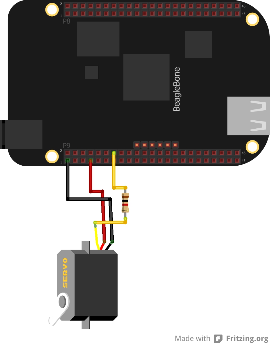
The direction of the servo motor's arm can be controlled by changing the duty cycle of the Beaglebone Black PWM signal applied to the pulse (yellow) line. In theory, the minimum pulse width should be 1 ms while the maximum pulse width is 2 ms. A 1.5 ms pulse width will turn the arm to the center position. But not all servo motors follow the exact same pulse widths. Some will have center positions at less than or greater than 1.5 ms. Thus you need to experiment with your own servo meter to know the exact pulse width for the center position. As for me, I'll stick with the standard 1.5 ms pulse width for the center position.
To begin with, we need to setup the Beaglebone Black PWM's period. The period should be larger than the max pulse width of 2 ms. We also need to set the polarity to a positive pulse. I wanted to set it to 20 ms so here's what I did:
root@arm:/sys/devices/class/pwm/pwmchip0/pwm0# echo 0 > polarity
root@arm:/sys/devices/class/pwm/pwmchip0/pwm0# echo 20000000 > period
root@arm:/sys/devices/class/pwm/pwmchip0/pwm0# echo 1 > enable
I sent a 1 ms pulse to turn it to -90° (left most position when facing the arm):
root@arm:/sys/devices/class/pwm/pwmchip0/pwm0# echo 1000000 > duty_cycle
root@arm:/sys/devices/class/pwm/pwmchip0/pwm0# echo 1 > enable
To turn it to 90° (all the way to the right), I sent a 2 ms pulse:
root@arm:/sys/devices/class/pwm/pwmchip0/pwm0# echo 2000000 > duty_cycle
root@arm:/sys/devices/class/pwm/pwmchip0/pwm0# echo 1 > enable
To turn it to the center position, I sent a 1.5 ms pulse:
root@arm:/sys/devices/class/pwm/pwmchip0/pwm0# echo 1500000 > duty_cycle
root@arm:/sys/devices/class/pwm/pwmchip0/pwm0# echo 1 > enable
TL, DR:
- To begin with beaglebone black pwm, download/copy/create a suitable device tree overlay
- Then compile the device tree overlay
- Then move the compiled device tree overlay to cape manager
- Next, identify the correct pwm chip
- Finally, echo values to polarity, period, duty cycle and enable!
Was this post useful? Drop a commment below!

