
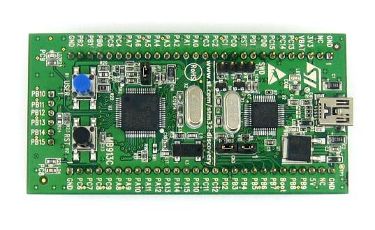
In my last post, I presented how to get started with the STM32F1 Discovery embedded evaluation board by downloading a package and running the example code. This time, I will teach you how to make a simple STM32F1 program from scratch.
This tutorial and my succeeding tutorials will be using Keil IDE for programming so download it if you haven't and the STM32Discovery Package. Also, you will need an internet connection for the first part of this tutorial to download the necessary run-time environment packages. The STM32F1 discovery board will be connected only when you are ready to flash the program to it but have it connected via the USB cable nonetheless.
That's it for the preliminaries. Here are the steps.
Step 1: Open Keil. Then click Project -> New μVision Project. A dialog window will appear. Name your project and save it. (Example, OBLed_example.uvprojx)
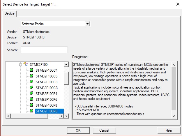
Step 2: The device manager window will appear. Click the (+) on STMicroelectronics then again on the STM32F1 Series then click on STM32F100RB. This is the microcontroller on the STM32F1 discovery board. Click OK.
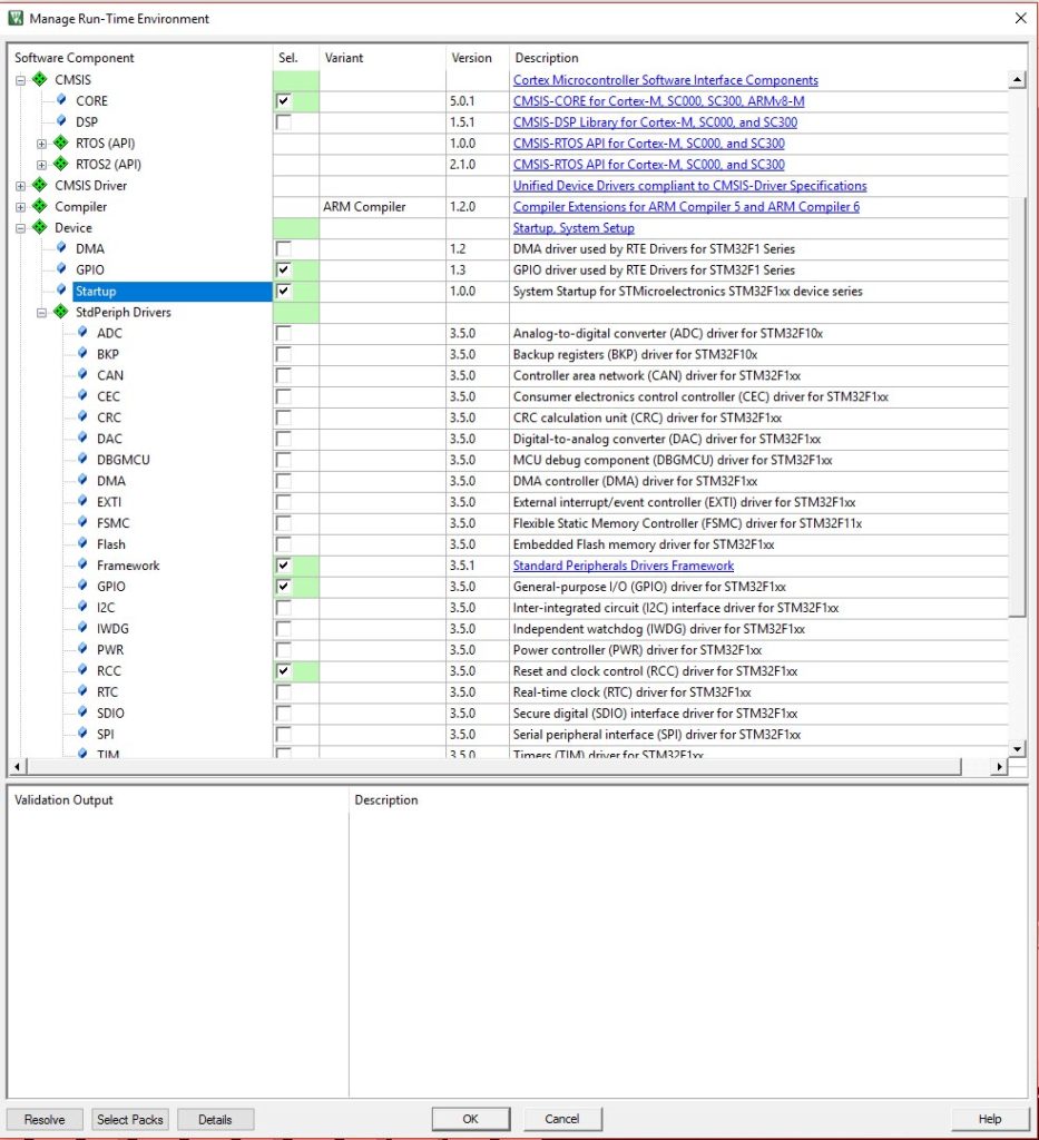
Step 3: The Run-Time Environment will appear. You will need to click on the checkbox for the following components for this example and then press OK:
- CMSIS -> CORE
- Device -> GPIO
- Device -> Startup
- Device -> StdPeriph Drivers -> Framework
- Device -> StdPeriph Drivers -> GPIO
- Device -> StdPeriph Drivers -> RCC
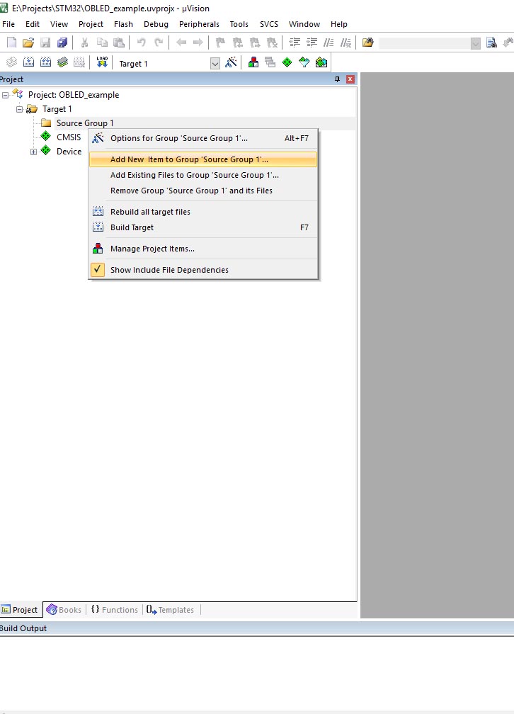
Step 4: Once the dialog box closes, you'll have an empty workspace. Right-click on Source Group 1 under Target 1 on the Project Explorer pane then select Add New Item to Group 'Source Group 1':
Step 5: Create a file named main.c on the same project folder.
Step 6: Paste this code then click Project -> Build Target (or press F7).
#include "stm32f10x.h"
#include "stm32f10x_rcc.h"
#include "stm32f10x_gpio.h"

GPIO_InitTypeDef GPIO_InitStruct;
void delay(int a);

int main(void)
{
  // Enable clock for GPIOC
  RCC_APB2PeriphClockCmd(RCC_APB2Periph_GPIOC, ENABLE);
  // Configure PC9 as push-pull output
  GPIO_InitStruct.GPIO_Pin = GPIO_Pin_9;
  GPIO_InitStruct.GPIO_Speed = GPIO_Speed_2MHz;
  GPIO_InitStruct.GPIO_Mode = GPIO_Mode_Out_PP;
  GPIO_Init(GPIOC, &GPIO_InitStruct);
  while (1)
 {
  // Turn on LED on PC9
  GPIO_ResetBits(GPIOC, GPIO_Pin_9);
  delay(500000);
  // Turn off LED on PC9
  GPIO_SetBits(GPIOC, GPIO_Pin_9);
  delay(500000);
 }
}

void delay (int a)
{
 volatile int i,j;
 for (i=0 ; i < a ; i++)
 {
  j++;
 }
 return;
}
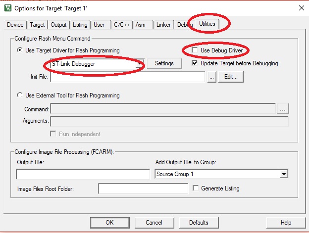
Step 7: You should see the line "0 Error(s), 0 Warnings (s). " on the Build Output window if everything was done right. Before we can download the program to the STM32F1 Discovery board, we need to configure flash programming first. Click Flash -> Configure Flash Tools. On the Utilities tab, uncheck Use Debug Driver and Select ST-Link Debugger under Use Target Driver for Flash Programming:
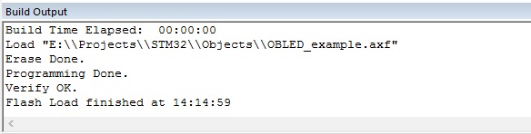
Step 8: Click OK to close the dialog and then press F8 to download the program to the board. If every thing is good then you will this on the Build Output window:
Step 9: Now press the reset button (the black button) on the STM31F1 discovery board and watch the PC9 LED flash!

