
The PIC16F877A microcontroller comes with a Capture Compare PWM (CCP) module which utilizes its 16-bit Timer1 module to generate or count pulses, among other things. I have already covered how to generate PWM in my previous tutorial. This time, we will look at how to implement capture and compare with PIC16F877A using the CCP module.
Capture Mode
When in capture mode, the value of Timer1 is copied to the CCPRx register when any of these four events happen:
- rising edge on CCP pin
- falling edge on CCP pin
- 4th rising edge on CCP pin
- 16th rising edge on CCP pin
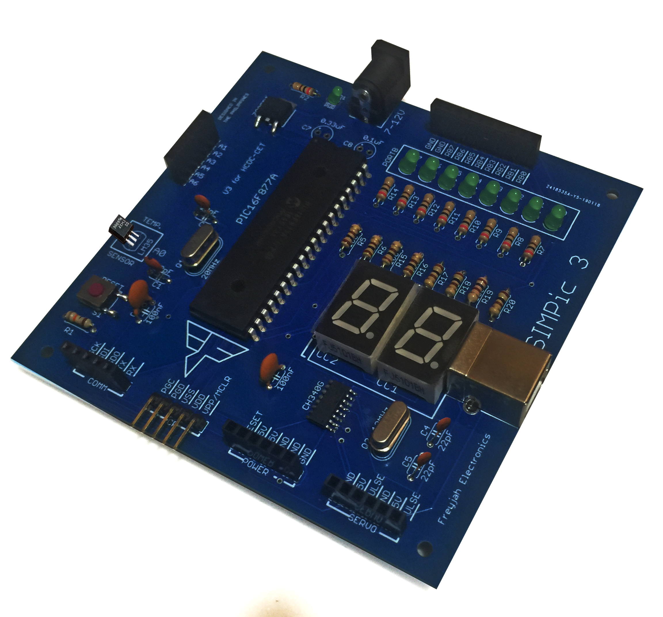
Note that there are two CCP pins, CCP1 on RC2 and CCP2 on RC1. Each CCP pin corresponds to a CCPxCON register:
In short, to capture on CCP1 pin (RC2) use CCP1CON. Otherwise, to capture on CCP2 pin (RC2) use CCP2CON.
To enable capture mode, you must follow these steps:
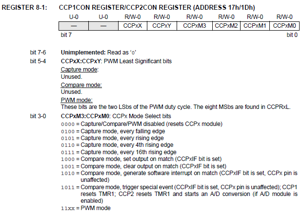
- Adjust the value of bits 3 to 0 of CCPxCON register to the desired capture mode: 0100 for every falling edge, 0101 for every rising edge, 0110 for every 4th rising edge and 0111 for every 16th rising edge.
- Make CCP pin input by setting the corresponding TRISC pin.
- Read the CCPRx register. Note that both Timer1 and CCPRx registers are 16-bit registers and is subdivided into TMR1H, TMR1L and CCPRxH, CCPRxL respectively.
Here is an example ASM code that captures the Timer1 value and displays it on PORTB:
#include <P16F877A.INC>

RES_VECT  CODE    0x0000            ; processor reset vector
    GOTO    START                   ; go to beginning of program

; TODO ADD INTERRUPTS HERE IF USED

MAIN_PROG CODE                      ; let linker place main program

START
    MOVLW b'00000100'
    MOVWF CCP1CON	    ;Capture Mode, every falling edge on RC2
    BSF STATUS,RP0	    ;Bank 1
    BSF TRISC,2		    ;Make RC2 input
    CLRF TRISB		    ;Make PORTB output
    BCF STATUS,RP0	    ;Bank 0
    BSF T1CON,TMR1ON	    ;Turn on Timer1
MAIN
    BTFSS PIR1,CCP1IF
    GOTO MAIN
    MOVF CCPR1L,W
    MOVWF PORTB
    GOTO MAIN

    END
What this code does is capture the value of Timer1 every time a falling edge pulse is detected at RC2. Since Timer1 and consequently, CCPR1, are 16-bit registers, we cannot copy their values to PORTB, which is an 8-bit register. What I did here is just copy the low byte (CCPR1L) to PORTB.
Compare Mode
In compare mode, the CCPR1 value is continuously compared to the Timer1 value. When the CCPR1 value is equal to the Timer1 value, the CCP1 pin (RC2) is either driven low, high or remain unchanged but with other effects. The event on match condition can be set using the same CCP1CON register.
To enable compare mode, follow these steps:
- Adjust the value of bits 3 to 0 of CCPxCON register to the desired event on match: 1000 to set CCP pin, 1001 to clear CCP pin, 1010 to generate an interrupt and 1011 to start A/D conversion.
- Make CCP pin output by clearing the corresponding TRISC pin.
- Load a value to CCPRx register that will be compared to the Timer1 value.
#include <P16F877A.INC>

RES_VECT  CODE    0x0000            ; processor reset vector
    GOTO    START                   ; go to beginning of program

; TODO ADD INTERRUPTS HERE IF USED

MAIN_PROG CODE                      ; let linker place main program

START
    MOVLW b'00001000'
    MOVWF CCP1CON	    ;Compare mode, set RC2 on match
    BSF STATUS,RP0	    ;Bank 1
    BCF TRISC,2		    ;Make RC2 output
    BCF STATUS,RP0	    ;Bank 0
    MOVLW 0xFF
    MOVWF CCPR1L            ;Let CCPR1 = 255
    BSF T1CON,TMR1ON	    ;Turn on Timer1
MAIN
    BTFSS PIR1,CCP1IF
    GOTO MAIN               ;Do nothing, wait for match
    BCF PORTC,2             ;Match condition, clear RC2
    END
What this code does is wait for a match between the CCP1RL (equal to 255 in this example) and the Timer1 value. When a match occurs, the RC2 pin should set. In order for us visualize the match again, the RC2 must be cleared after the match occured.
Practical Application of Capture and Compare
One good practical application of capture and compare is pulse counting. While pulse counting can be implemented using Timer0's counter mode, it is limited to 8-bit values. The 16-bit Timer1 value has a higher resolution and thus can count faster pulses.
An article on a frequency counter PIC project will be published detailing the practical application of capture and compare.

