
Introduction
This week’s Arduino project is a classic one and ideal for beginners. Here I will be showing how to build a simple clap switch for an RGB LED strip. Basically, a microphone captures the sound of the clap and converts it to a voltage. The Arduino processes that voltage and then changes the color of the RGB LED strip.
What You’ll Need
- Arduino Microcontroller (Nano in this case but UNO is possible too)
- Microphone breakout board
- Connecting wires (jumper)
- RGB LED strip (12V)
- 3 x 2N2222A NPN Transistor
- 12V power source
Wiring Diagram
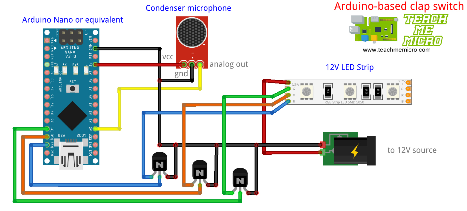
The condenser microphone converts sound to an analog voltage. My Arduino microphone tutorial covers the basics of how condenser microphones work. The voltage from the microphone is read by the ADC of the Arduino and converted it to a digital value.
You can use the analogReadSerial sketch (File> Examples>Basics) first to know the value of your clap sound. After that, replace the value of the threshold variable in the sketch below.
This clap switch project listens to three claps 1 second apart. When this condition is met, the RGB LED strip changes color. Moreover, the sequence of colors follows R-O-Y-G-B-V.
A particular LED turns on when the voltage drop across it is zero. For example, a high pulse from Arduino's D9 will turn on the transistor resulting in the green LED turning on. The 2N2222A transistor in this project was enough to handle the current requirements of the LED strip.
You can use a 5V or a 12V LED strip as long as you have the power source for it. My diagram uses a 12V LED strip so I needed to have a separate supply for the Arduino board.
Sketch/Code
/*
 * Clap Switch for RGB LEDs using Arduino
 *
 * by: R. Pelayo
 * Created: February 13, 2020
 *
 * Full project tutorial on: teachmemicro.com/clap-switch-rgb-led-arduino
 */

#define threshold 200  //change this according to your clap sound
int red = 10;
int green = 9;
int blue = 11;
int mic = A0;
int sound_value;
int clap_counter = 0;
int color_counter = 0;

void setup() {
  pinMode(red,OUTPUT);
  pinMode(green,OUTPUT);
  pinMode(blue,OUTPUT);
}

void loop() {
  int sound_value = analogRead(mic);
  if(sound_value > threshold){
    clap_counter++;
    if(clap_counter > 2){
      clap_counter = 0;
      color_counter++;
      if(color_counter > 5) color_counter = 0;
      changeColor();
    }
  }
  delay(1000);
}

void changeColor(){
  switch(color_counter){
    case 0: //display red
      analogWrite(red,255);
      analogWrite(green,0);
      analogWrite(blue,0);
    case 1: //display orange
      analogWrite(red,210);
      analogWrite(green,100);
      analogWrite(blue,0);
    case 2: //display yellow
      analogWrite(red,255);
      analogWrite(green,255);
      analogWrite(blue,0);
    case 3: //display green
      analogWrite(red,0);
      analogWrite(green,255);
      analogWrite(blue,0);
    case 4: //display blue
      analogWrite(red,0);
      analogWrite(green,0);
      analogWrite(blue,255);
    case 5: //display violet
      analogWrite(red,255);
      analogWrite(green,0);
      analogWrite(blue,255);
  }
}
Here, I set the threshold value to 200. Every time the voltage from the microphone reaches this level, a variable (clap_counter) increments. When this variable reaches a value of three, the function to change color is invoked, and another variable (color_counter) increments. The color_counter variable is used for knowing which color in the sequence to be displayed.

