
LoRa is a promising low-power, long-range wireless transmission protocol developed by Semtech as part of the emergence of the Internet of Things (IoT). Simply put, it is a method for sending data separate from WiFi, Zigbee, or Bluetooth. Its low power consumption amidst a very long range of transmission (up to 10 km) makes it a very good choice for microcontroller systems.
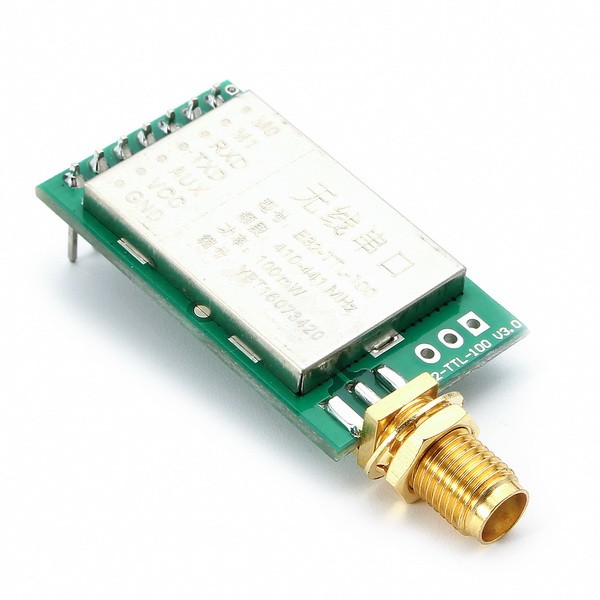
The E32-TTL-100 SX1278 LoRA Module
I managed to grab one of those LoRa modules that litter the market today. Mine’s an E32-TTL-100 module which is said to be based on Semtech’s SX1278. Here are the specifications for the module:
- Module size:21*36mm
- Antenna type: Standard SMA antenna (FREE)
- Power supply:2.3V-5.5V DC
- Communication level:5.2V(max)
- Transmission distance:3000m(max)
- Maximum power:2dB(100mW)
- Air rates:2.4Kbps
- Emission current:130mA @ 100mW
- Receiving current:13.5mA @ Mode 0, Mode 1
- Sleep Current:2.0uA(M1=1,M1=0)
- Emission length:256 Byte
- Receive length:256 Byte
- Communication Interface: UART
- RSSI support: Yes
- Working frequency:410MHz-441MHz(Default 433MHz)
- Operating temperature:-30?~+85?
- Receiver sensitivity:-130dBm @ 1.2Kbps
A range of 3km! I doubt this is possible for non-LOS (line of sight) but let’s see.
The module has 7 pins as shown:
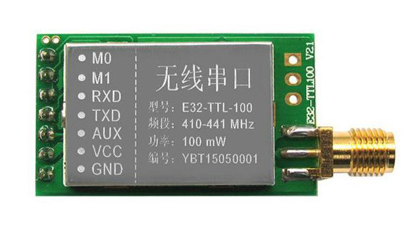
It’s UART-based so I think RXD, TXD (and of course VCC and GND) are self-explanatory. Let me try to explain the M0, M1, and AUX pins.
Configuring Modes
It turns out, M0 and M1 are used to set the modes of the module. There are four modes: normal, wake-up, power-saving, and sleep. Here’s a useful table:
| Mode | M1 | M0 | Explanation |
| Normal | 0 | 0 | UART and the wireless channel is good to go |
| Wake-Up | 0 | 1 | Same as normal but a preamble code is added to transmit data for waking up the receiver. |
| Power-Saving | 1 | 0 | UART is disabled and wireless is on WOR(wake on radio) mode which means the device will turn on when there is data to be received. Transmission is not allowed. |
| Sleep | 1 | 1 | Used in setting parameters. Transmitting and receiving are disabled. |
The AUX Pin
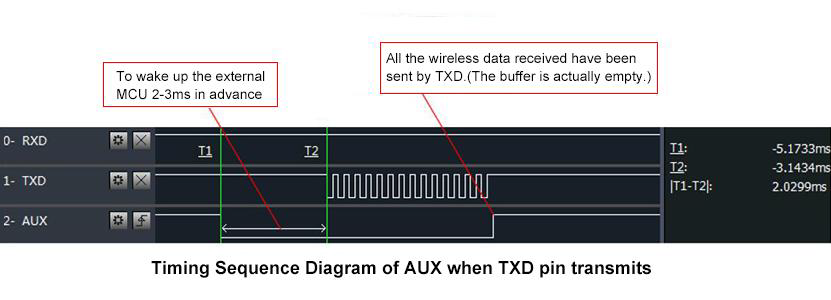
The AUX pin serves as a flag for checking if the data has been sent or when data has been received. It’s also used to check if the module is still in self-check procedure which happens during power-on and exit from sleep mode.
When the module is idle, the AUX pin stays high. If there is data is to be sent, the AUX pin stays low 2-3 ms prior to the data being sent to the transmit buffer. The AUX pin goes back to high if the transmit buffer is clear (i.e., the data has been sent wirelessly). Similarly, the AUX pin goes low when there is data on the receive buffer.
The logic states of the AUX pin are summarized below:


Parameter Setting
As mentioned, when the module is in sleep mode (M0=M1=1), we can change some options like baud rate, UART format, etc. The commands for changing parameters must be sent using 9600 baud, 8N1.
The format for changing parameters is 0xC0/0xC2 ADDH ADDL SPED CHAN OPTION. When you want the parameters to be saved to EEPROM, use 0xC0. Otherwise, use 0xC2. The rest are bytes with the following possible values:
| Item | Description | Notes |
| ADDH | Module high address byte (00h by default) | |
| ADDL | Module low address byte (00h by default) | |
| SPED | UART Baud Rate and Air Data Rate | See bit descriptions below. |
| CHAN | Operating Frequency (0x00 to 0xFF corresponding to 410 to 441 MHz. Default is 0x17 - 433 MHz) | |
| OPTION | Other options | See bit descriptions below. |
SPED Bit Descriptions
| Bit 7 and 6 | Bit 5, 4, 3 | Bit 2, 1, 0 |
| UART Parity | UART Baud Rate | Air Data Rate |
| 00:8N1(default) 01:8O1 10:8E1 11:8N1(equal to 00) |
000:1200bps
001:2400bps 010:4800bps 011:9600bps(Default) 100:19200bps 101:38400bps 110:57600bps 111:115200bps |
000:0.3kbps
001:1.2kbps 010:2.4kbps(Default) 011:4.8kbps 100:9.6kbps 101:19.2kbps 110:19.2kbps(equal to 101) 111:19.2kbps(equal to 101) |
OPTION Bit Descriptions
| Bit 7 | Bit 6 | Bit 5,4,3 | Bit 2 | Bit 1 and 0 |
| Fixed Transmission | I/O Drive Mode | Wireless Wake-up Time | FEC (Forward Error Correction) Switch | Transmission Power |
| 0: transparent transmission (default)
1: fixed transmission (first three bytes can be used as high/low address and channel) |
0: TXD, RXD, AUX are open-collectors
1: TXD, RXD, AUX are push-pulls/pull-ups |
000:250ms(default)
001:500ms 010:750ms 011:1000ms 100:1250ms 101:1500ms 110:1750ms 111:2000ms ) |
0:Turn off FEC
1:Turn on FEC(Default) |
00: 20dBm(Default)
01: 17dBm 10: 14dBm 11: 10dBm |
So for example, you want to change the UART baud rate to 115200, 8N1 mode, air data rate to 19.2kbps, use the default 433 MHz operating frequency, fixed transmission mode, push-pull pins, 250 ms wake-up time, FEC on, and 20 dBm transmission power. Set M0 and M1 and send the following data through UART:
0xC0 0x00 0x00 0x3D 0x17 0xC4
For reading the current options, send the commands:
0xC1 0xC1 0xC1
This is for reading the version number:
0xC3 0xC3 0xC3
And for resetting the module:
0xC4 0xC4 0xC4
Bob Chan has created an example sketch for using the E32-100 LoRa module with the Arduino. The library is available at his github repository. His library allows you to change parameters as I have discussed.
To use the above library, follow this connection:
| UNO/NANO(5V mode) | E32-TTL-100 | |
|---|---|---|
| D7 | <---------------------> | M0 |
| D8 | <---------------------> | M1 |
| A0 | <---------------------> | AUX |
| D10(Rx) | <---> 4.7k Ohm <---> | Tx |
| D11(Tx) | <---> 4.7k Ohm <---> | Rx |
I hope you found this tutorial useful. If you have questions, kindly drop a comment below.

