
The ESP32 has become one of my favorite microcontrollers as it's compact, relatively cheap, and contains 125% higher memory than an Arduino UNO.
I use the ESP32 almost exclusively for web server projects and this one is no different. A sensor measures the turbidity of water and the output is viewable through a web application on the ESP32.
Materials
- ESP32S Breakout Board
- DFRobot Analog Turbidity Sensor
- Miscellaneous (connecting wires, breadboard, power source)
ESP32S Breakout Board
The ESP32 is an upgrade over the popular ESP8266 WiFi SOC. I’ve already shown how to code the ESP32 using the Arduino platform. Note however that that tutorial uses a DOIT ESP32 DEVKIT, while here I am using a NodeMCU ESP32S. They may look the same but they have different pinouts. Here's the NodeMCU ESP32S pinout:
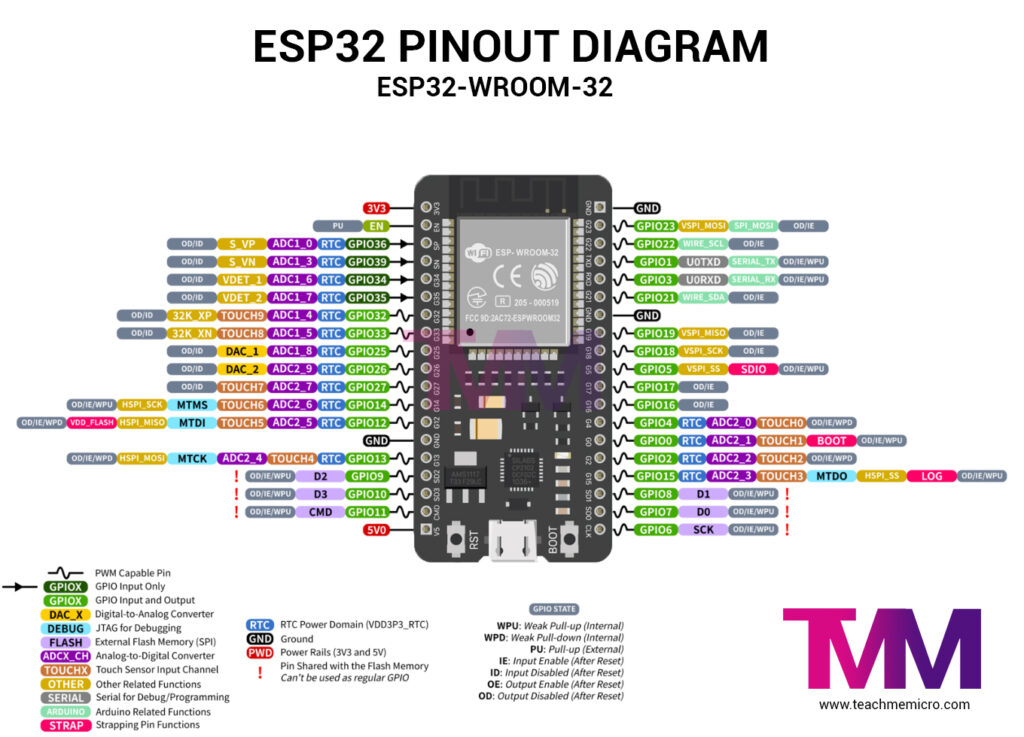
The ESP32 board contains a microUSB port and can be powered through it. Note that all of its pins operate at 3.3V!
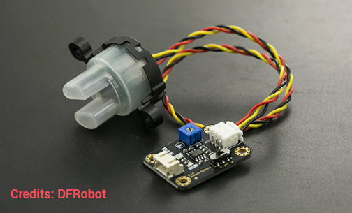
Analog Turbidity Sensor
DFRobot’s turbidity sensor contains two parts: the sensor to be submerged and the controller board.
Controller Board
The controller board contains a switch for changing between digital or analog modes. In digital mode, the sensor gives a low voltage when the water is muddy. "Muddy" in this case depends on the sensitivity of the controller which is adjustable through the blue potentiometer.
In analog mode, the board gives out a voltage that varies with the turbidity of water. The muddier the water, the lower that voltage.
Shown below is the schematic of the controller board:
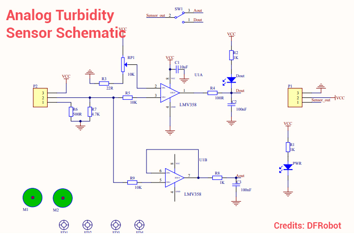
The controller features two LM358 operational amplifiers. The upper op-amp is a comparator that produces a low voltage whenever the threshold voltage from the sensor exceeds that of the reference voltage through the RP1 potentiometer. A diode lights up (Dout) when this happens.
The lower operational amplifier is a buffer that conditions the voltage from the receiver IR LED.
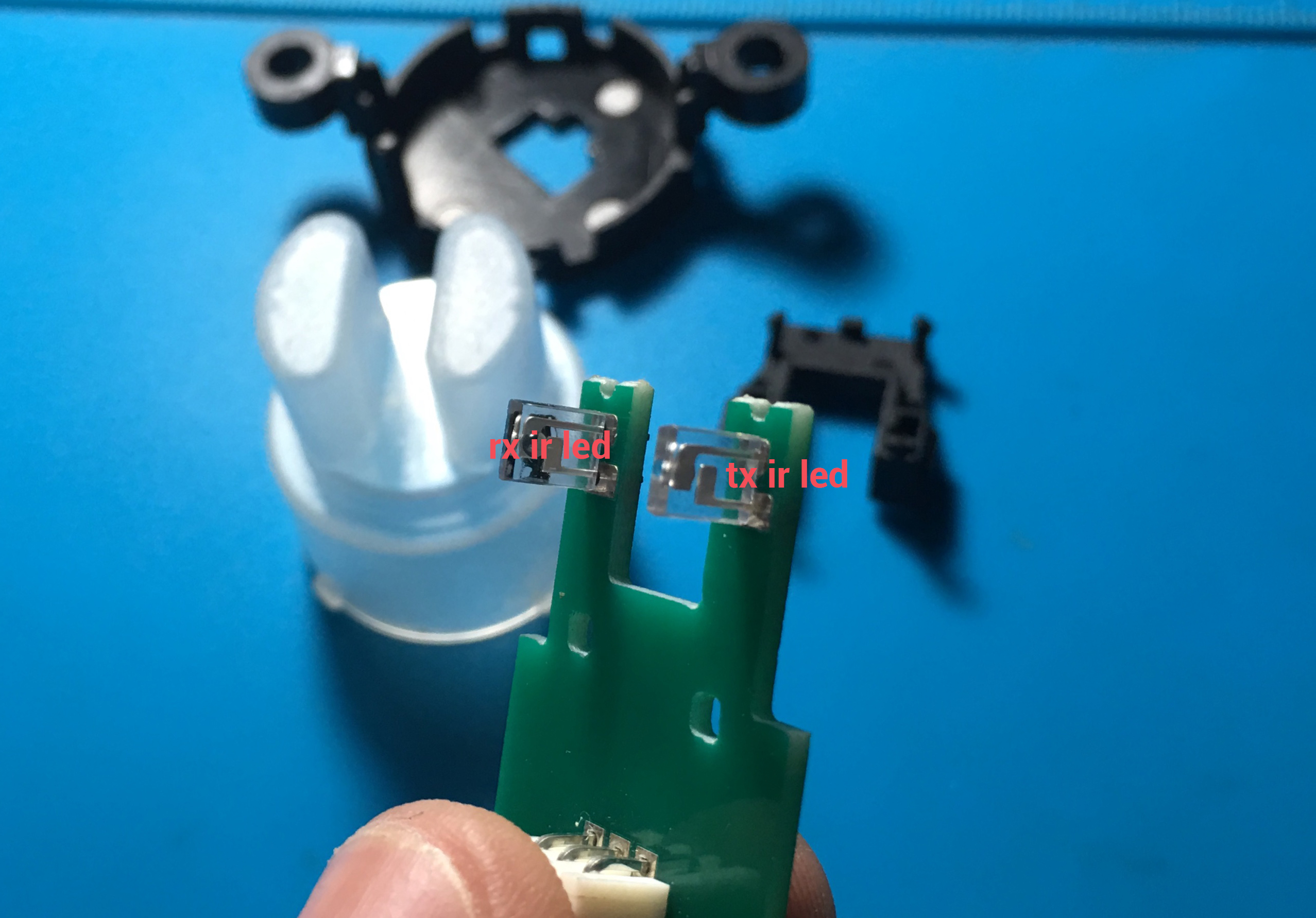
Submersible Sensor
The sensor includes a semi-transparent plastic case and a top cover. Removing the top cover reveals a small circuit board containing an infrared transmitter and receiver facing each other. A trimmer potentiometer is also on the board seemingly for adjusting the sensitivity of the IR receiver.
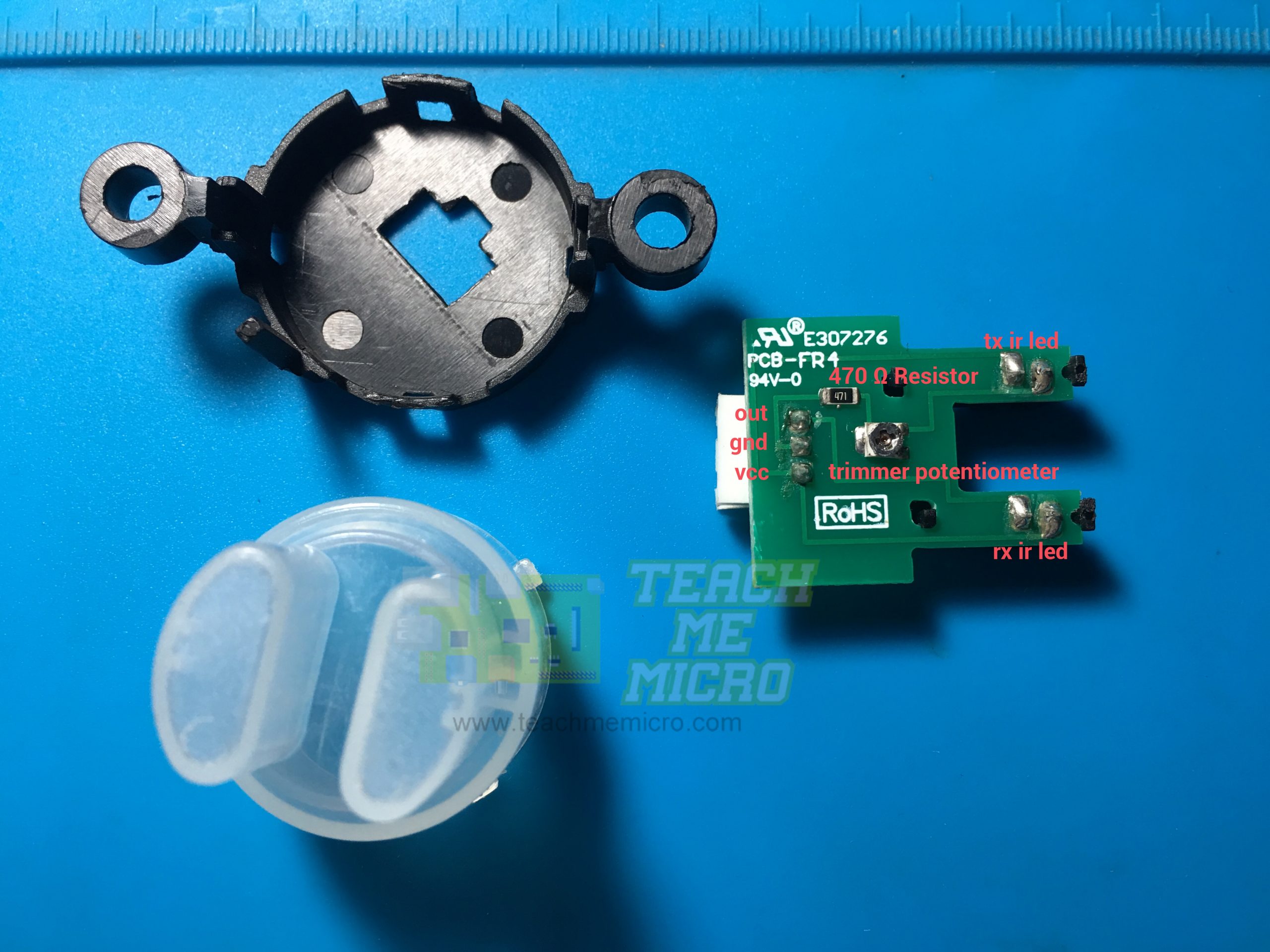
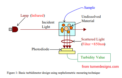
The sensor works through Tyndall effect, which is the scattering of light in water due to foreign particles like dirt, etc. When the water is clear, the receiver IR LED receives the maximum amount of radiation from the transmitter IR LED. As the water gets muddier, the radiation in the receiver IR LED gets lesser. Thus, at clear water, the sensor board produces a higher current and vice versa.
Turbidity, per international standards, is measured according to Nephelometric Turbidity Units (NTU) through a Nephelometer. DFRobot, claims that you can calculate the NTU output using this sensor by using this diagram and the included formula:
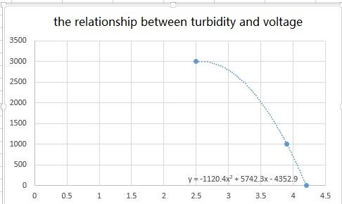
This is the same formula on my Arduino turbidity sensor tutorial two years ago. However, I learned that Nephelometers place the receiver at 90 degrees relative to the transmitter:
This is different from the transmitter-receiver setup in my turbidity sensor. DFRobot didn’t give a source of their formula or how they arrived at it. Because of this vagueness, for this project, I will not be using that formula anymore.
Wiring
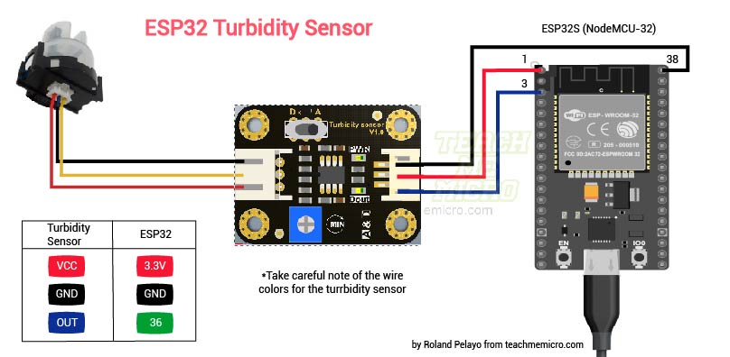
This project uses the turbidity sensor in analog mode since it gives out more possible values. Thus, the output pin of the controller connects to an analog pin (to which the ESP32 has a lot of, btw). I chose to connect the output pin to GPIO36.
The official documentation of the sensor states that the sensor operates at 5V. But looking at the schematics, I see no problem for using 3.3 V (which is the operating voltage of the ESP32). Yes, the ADC calculations will be different but it's just a matter of changing the calculations from 5V to 3.3V.
Note that there is a correct way of wiring the sensor to its controller (it won’t work otherwise). See image below:

Code/Sketch
The code is too long to be on this article so see it in my repository: https://github.com/kurimawxx00/esp32-turbidity The next sections are explanations of the parts of the code.
Reading Sensor Value
Since I will not be using NTU as a turbidity unit, I had to construct a way to display the data from the sensor. From tests, the sensor gives out around 2.25 volts when the water is clear and 0 volts at the muddiest water. This corresponds to an ADC value of approximately 2800, from:
![]()
So I mapped this range to five levels using Arduino’s map function
int val = analogRead(36);
turbidity = map(val, 0, 2800, 5, 1);
This analog-to-digital conversion part runs every time the web client visits the page “data”.
server.on("/data", [](){
  delay(100);
  int val = analogRead(36);
  turbidity = map(val, 0, 2800, 5, 1);
  text = (String)turbidity;
  Serial.println(val);
  server.send(200, "text/plain", text);
});
Although the part above is on setup() and not loop(), it still runs repeatedly because of a javascript function. More on this later.
Establishing a WiFi Connection
Creating a web server through WiFi is easier thanks to ready-made Arduino libraries:
#include <WiFi.h>
#include <WiFiClient.h>
#include <WebServer.h>
For those who'd like to use this code, kindly change these to your own WiFi SSID and password.
const char* ssid = "<your WiFi SSID>";
const char* password = "<your WiFi password>";

WebServer server(80);
The rest of the configurations are inside setup():
Serial.begin(9600);
WiFi.mode(WIFI_STA);
WiFi.begin(ssid, password);
Serial.println("");
// Wait for connection
while (WiFi.status() != WL_CONNECTED) {
  delay(500);
  Serial.print(".");
}
Serial.println("");
Serial.print("Connected to ");
Serial.println(ssid);
Serial.print("IP address: ");
Serial.println(WiFi.localIP());
Creating the App Page
Every time the web client visits the home page (whose IP address is on the Serial Monitor during reset), the ESP32 serves a string named “page”.
server.on("/", []() {
  server.send(200, "text/html", page);
});
The “page” string is on a separate “mainpage.h” file.
The page also contains javascript code for data processing and animations, contained in a string named “javascript”.
server.on("/jscript.js", []() {
  server.send(200, "text/javascript", javascript);
});
The “javascript” string is also on a separate file, named “jscript.h”.
A <div>container changes color with the turbidity level. The turbidity level is fetched from the “data” page through AJAX with one-second intervals per request. Here is the javascript part, found on the jscript.h file.
$(document).ready(function(){
 setInterval(getData,1000);
 function getData(){
     $.ajax({
     type:GET,
     url:data,
     success: function(data){
        var s = data.split('-');
        var t = parseInt(s);
        switch(t){
            case 1:
                $('#turbidity').css('background-color','white');
                break;
            case 2:
                $('#turbidity').css('background-color','#EEE1DF');
                break;
            case 3:
                $('#turbidity').css('background-color','D5BDB8');
                break;
            case 4:
                $('#turbidity').css('background-color','#886058');
                break;
            case 5:
                $('#turbidity').css('background-color','#4D2820');
                break;
        }
        $('#tur-value').val(s[0]);
     }
     }).done(function() {
        console.log('ok');
     })}});;
If you look at the “page” string, you’ll also find the styling of the app. I tried to create a separate CSS file just like how I created a separate javascript file. But the ESP32 keeps giving connection timeouts, the reason for being is still unknown as of this writing. Nevertheless, I went with what works well and that is by including the styling in the HTML code inside “page”.
There are images on the app but none of them are hosted by the ESP32. Them, alongside with javascript libraries, are from external CDNs. This means the app will work only when the ESP32 has an Internet connection.
Project Output
Screenshot of the application:

The app in real-time:
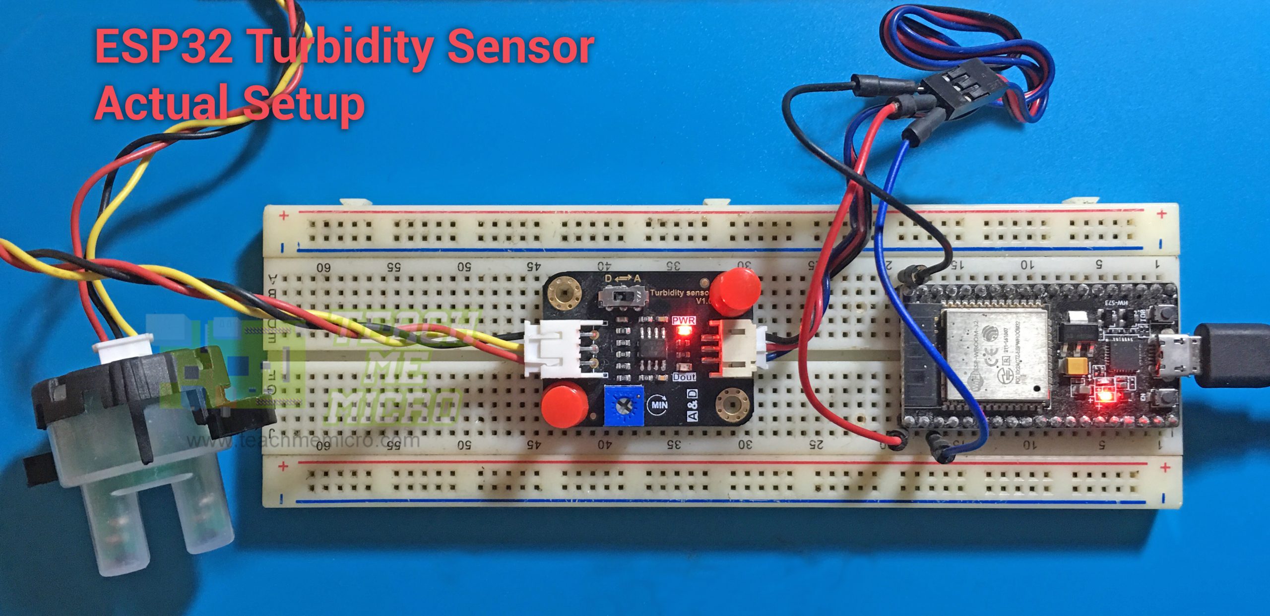
Actual setup:
My hope is that someone will find this project useful. Thanks for visiting!

