
There are a lot of Arduino-compatible boards but most of them are essentially clones. These clones are cheaper, yes, but why buy them if you can have boards that can give you MORE? A LOT MORE.
Bluno M0 Specifications
I thought that the "Bluno M0 Mainboard" was just a knock-off of the (now retired) Arduino M0 but I was wrong. In fact, the only similarity between the two is that they are both 32-bit microcontroller boards. Here are their specifications compared:
|
Specs |
Bluno M0 | Arduino M0 |
|
Microcontroller |
ARM Cortex M0 Nuvoton NUC123ZD4AN0 | ARM Cortex M0 ATSAMD21G18 |
|
No. of I/O Pins |
31 |
20 |
|
I/O Pin Voltage |
5V |
3.3V |
| Flash (Program) Memory |
68KB |
256KB |
|
PWM Pins |
6 (2 are soft PWM) |
12 |
|
Clock Speed |
72 MHz |
48 MHz |
| Other Features | SPI, I2C, I2S (!), dual USB ports, Bluetooth |
SPI, I2C, DAC |
They are clearly two different hardwares albeit the name similarity.
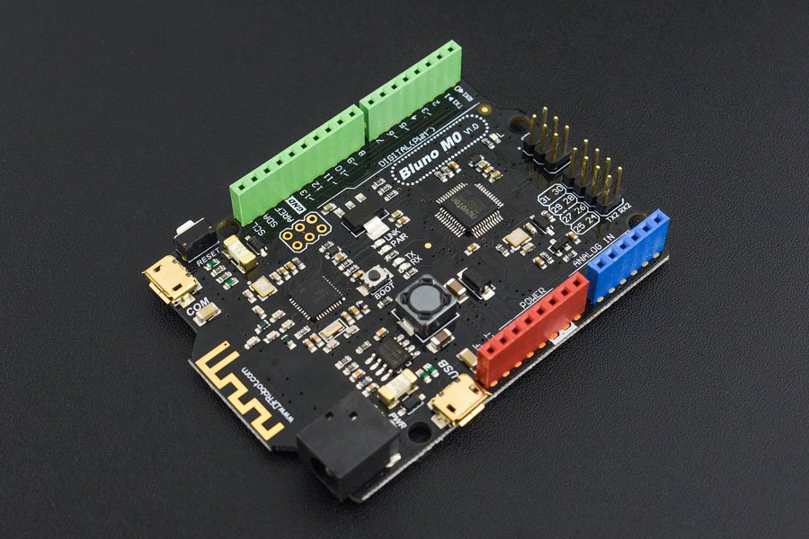
The thing that captured my attention about the Bluno M0 is its features. Besides the embedded CC2540 Bluetooth chip, it also supports I2S which is the I2C equivalent for audio. This means we can produce high-fidelity audio with this board IF we add an I2S decoder chip like the WM8978. More on that in future posts.
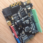
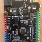
Board Layout
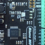
Here’s the board’s overview:
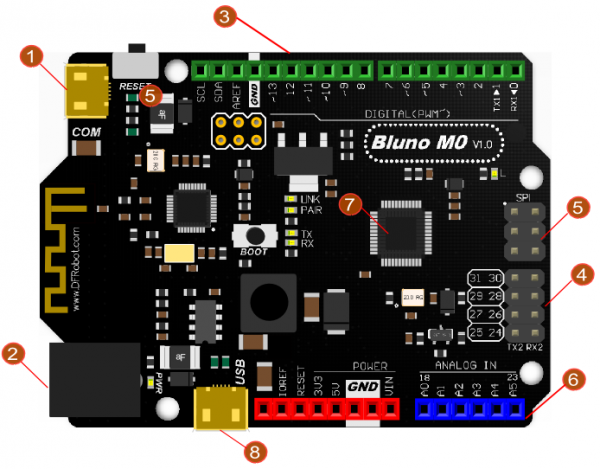
1 - USB COM Port. This is the main port to connect to a PC. Also the Bluetooth and Hardware Serial Port 1.
2 - Power Supply Port. Just like an Arduino UNO, this port accepts 7-12 V.
3 - Digital I/O Pins. Just like the Arduino boards.
4 - More Digital I/O Pins. But with male headers.
5 - NOT ICSP. But SPI pins.
6 - Analog Pins.
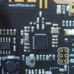
7 - Nuvoton NUC123ZD4AN0
8 - Second USB Port. If you need another serial port to connect to a PC.
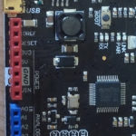
Not numbered are five LEDs: LINK, PAIR, TX, RX, and L. The LINK LED turns on if the board is connected to another Bluetooth device. The PAIR LED turns on if the board is paired. Of course, similar to the Arduino, TX and RX LEDs signal UART activity and L is connected to D13.
Pressing and holding the BOOT button makes the Bluno M0 go into firmware update mode. The updating is done with the help of special software. For older OS (Windows 7 and below), this binary file is used instead.
Programming the Board
The Bluno M0 is programmed using Arduino IDE. To add this board to the IDE, we need to add the DFRobotDuino core.
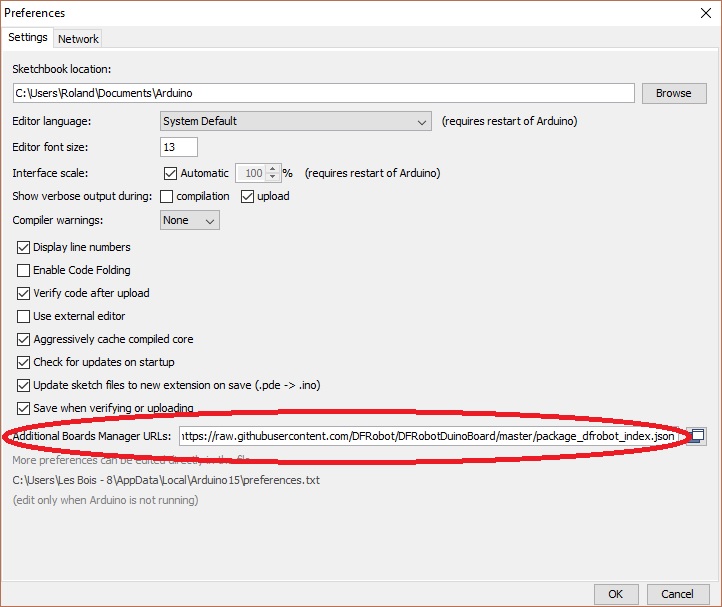
Open Arduino IDE and go to File > Preferences. On the dialog that appears, find the Additional Boards Manager URLs field and paste the URL of this link.
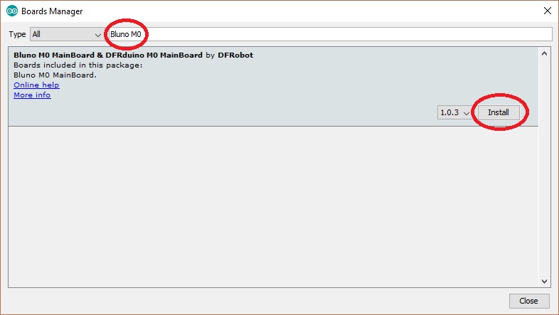
Click Ok. Then go to Tools > Board > Boards Manager. On the search field, type Bluno M0. Click the results that appear and click the Install button.
When everything was done correctly, the Bluno M0 board should now appear on the list of boards in Tools > Board.
I used this sample code to test my Bluno M0 board:
int LED = 13;
void setup(){
    pinMode(LED, OUTPUT);
}

void loop(){
    digitalWrite(LED, HIGH);
    delay(500);
    digitalWrite(LED, LOW);
    delay(500);
}
The Bluno M0’s drive is installed automatically when I connect it via microUSB cable to my Windows 10 PC. If you are experiencing problems, download the driver.
But of course, you can ditch the cable entirely when programming the board if your computer has Bluetooth. Just follow my instructions on how to create a Bluetooth serial interface with your PC and then you upload the code to your Bluno M0 wirelessly. Cool!
Images
Overall, I found the Bluno M0 a better option than purchasing an Arduino UNO plus a Bluetooth module or shield. I am actually guilty of this because that’s exactly my setup on my Bluetooth RC car project. As I am writing this, lots of Bluetooth-based projects using the Bluno M0 are popping into my brain. Care to share yours?

