
As a lifelong PIC fan, I was super thrilled when Microchip sent me a free unit of their Curiosity HPC development board. I’ve been working on PICs for years by just mounting them on breadboards and using PICKit to flash programs. This takes time and so when I’m faced with urgent projects, I had to switch to an ATMega/Arduino. Will the Curiosity help reduce development time? Let’s find out.
Close Look
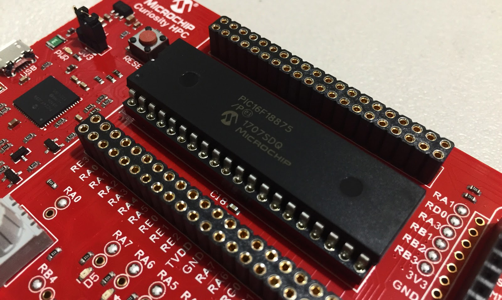
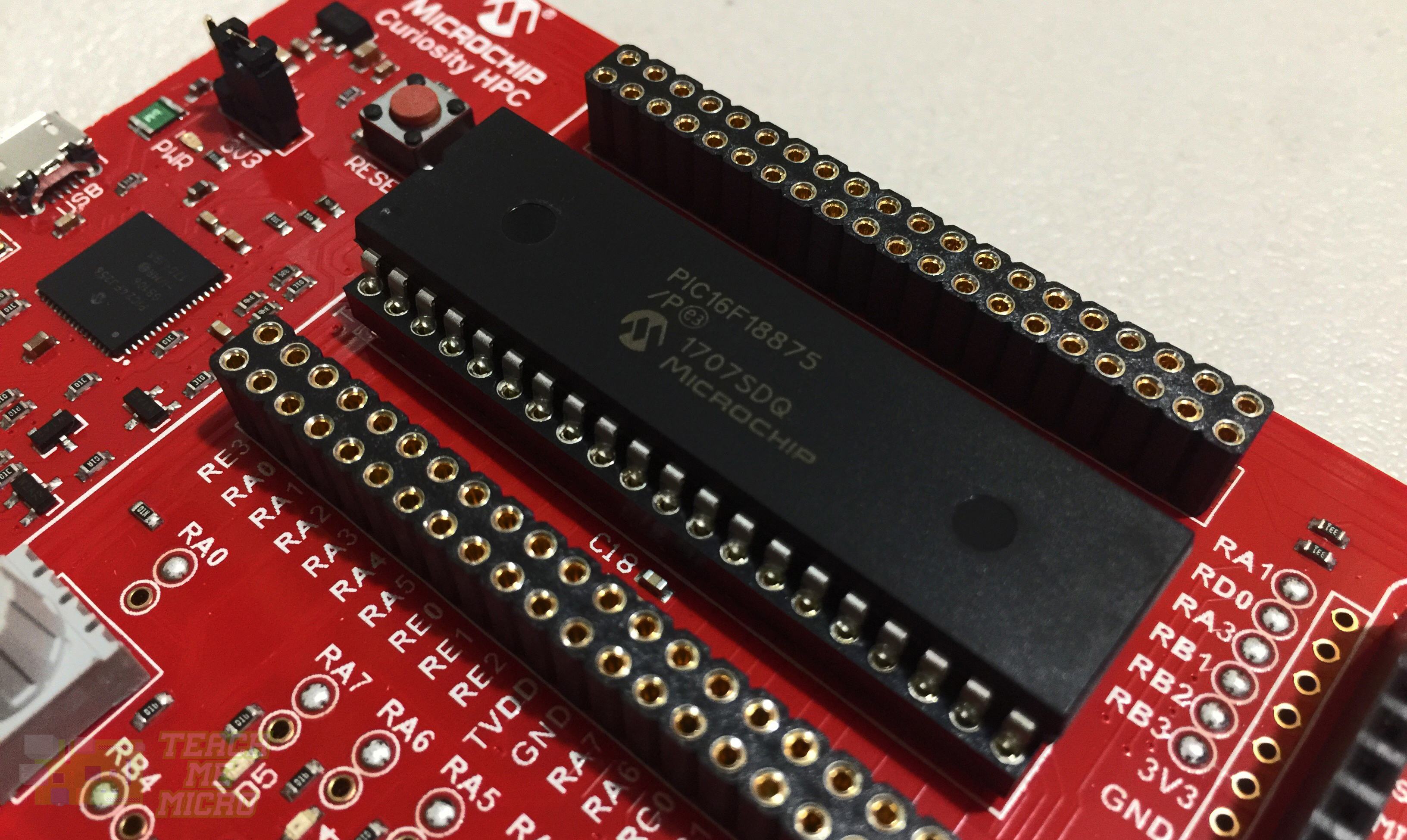
I found out that Microchip offers 8-bit, 16-bit and 32-bit curiosity boards. Mine is the 8-bit High Pin Count (HPC) version featuring the PIC16F18875. This microcontroller is a modern midrange device from Microchip with features that make the 877A look primitive. I’ll be writing a series of tutorial for the 16F18875 in the nearest future.

[the_ad id="3059"]
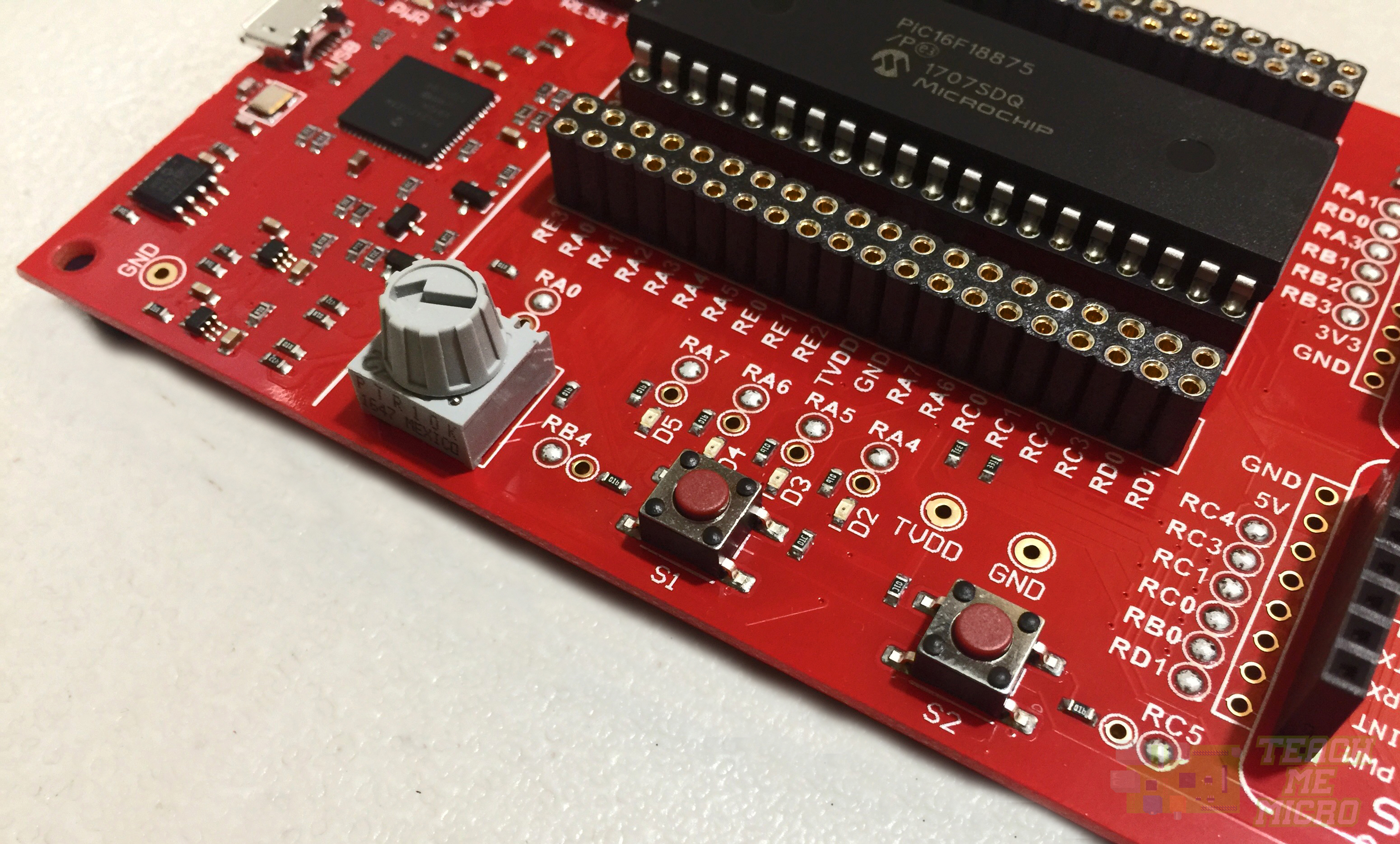
The two user buttons at the bottom part are wired to pins RB4 and RC5 in a normally-high setting (according to the datasheet). Above the buttons are four LEDs, wired to RA4, RA5, RA6 and RA7. There’s also a potentiometer wired to RA0 as shown.
The 40-pin PICs seem to have the same pin mapping so this could mean other 40-pins (say, 16F877A) can replace the included 16F18875.
The two row female headers could be very helpful during development stages. One gripe I had with the Arduino is that its almost impossible to connect two wires to a single pin. Looks like Microchip had that in mind when designing the Curiosity.
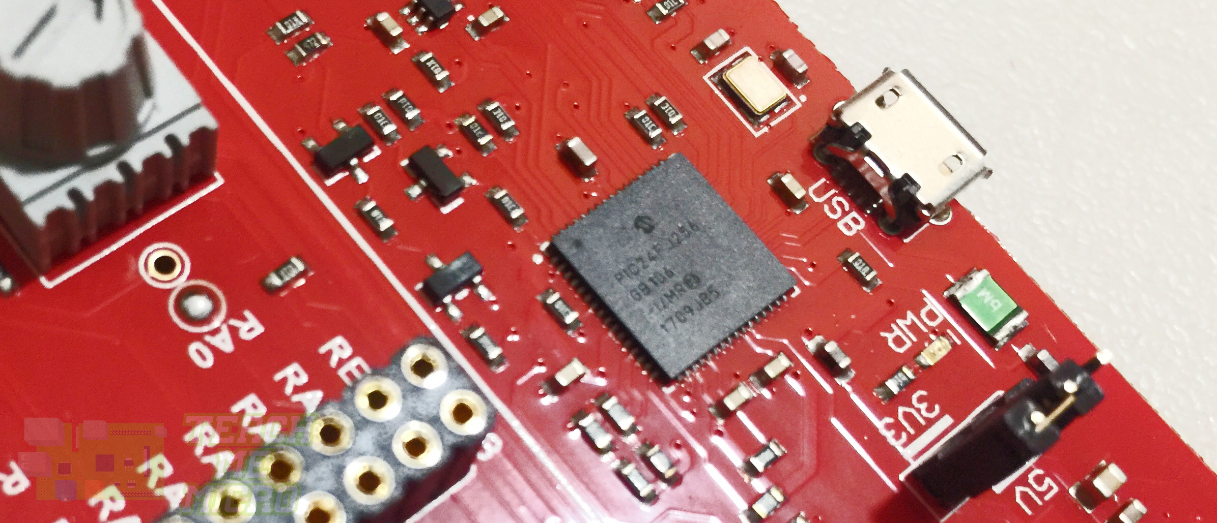
On the left side is the microUSB port, 5V to 3.3V jumper and a PIC24J256 to handle USB communication.
[the_ad id="3059"]
There are also two mikroBUS ports on the right side of the board:
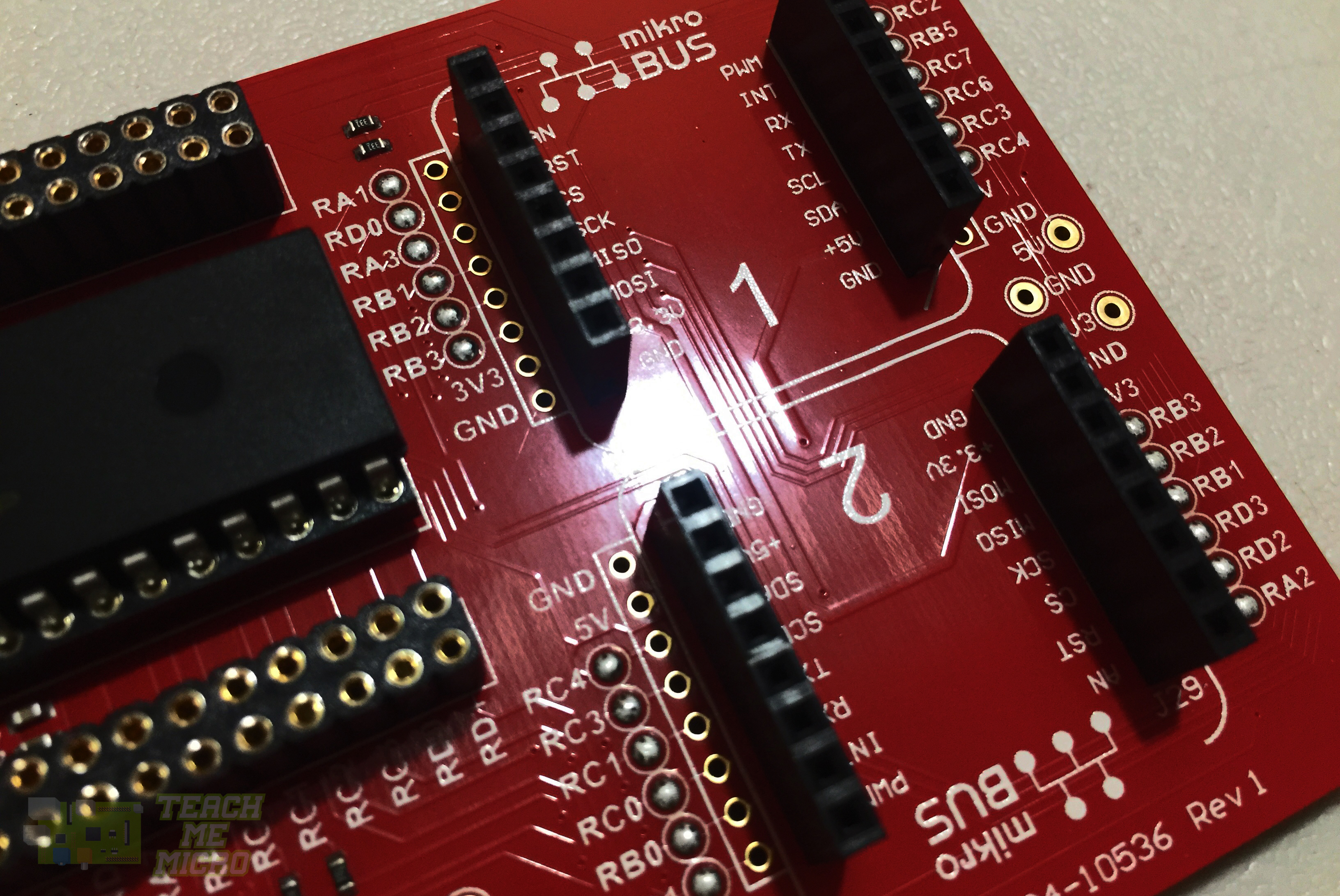
I can’t tell you more about mikroBUS right now because it’s the first time I’ve encountered it. But, it looks like it works similar to Arduino shields. In fact, my Curiosity package came with a Weather Click:
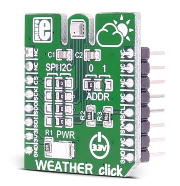
I’ll be writing another tutorial for using the Weather Click with the Curiosity board.
Setting Up the Curiosity HPC with MPLABX
There is reason to believe that the Curiosity board is designed to be seamless with Microchip’s MPLABX environment. If you are following this article as a guide, you must download MPLABX first.
[the_ad id="3059"]
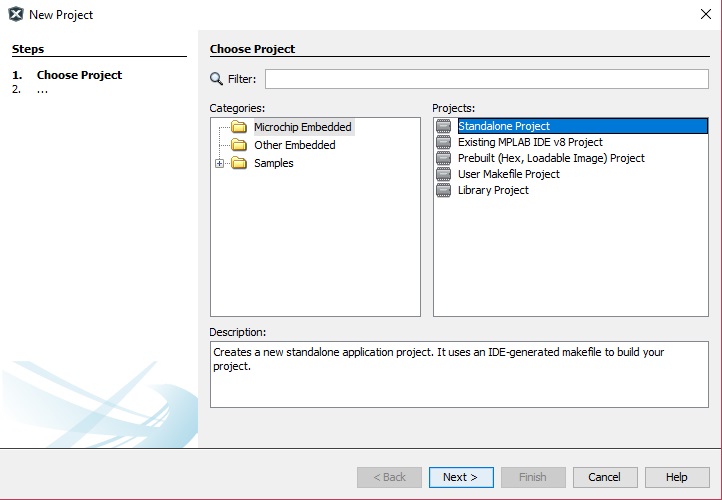
First, I connected the Curiosity on my PC using a microUSB cable. The green power LED now turns on. Then, I opened MPLAB X and created a new standalone project:
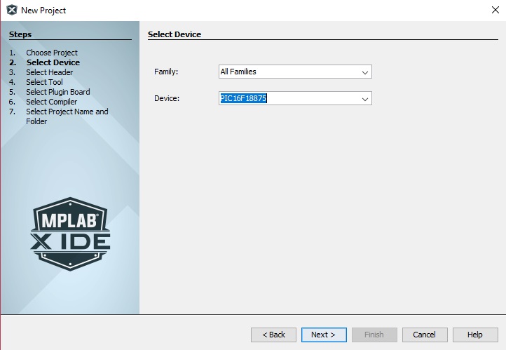
Then I selected the PIC on the board, PIC16F18875:
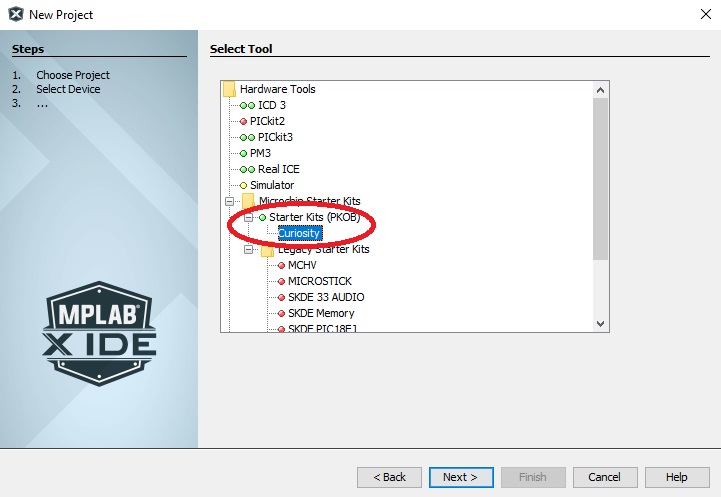
The Curiosity should show up in the Tools pane:
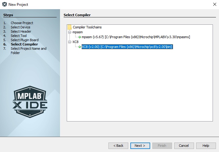
I chose XC8 as my compiler for this example:
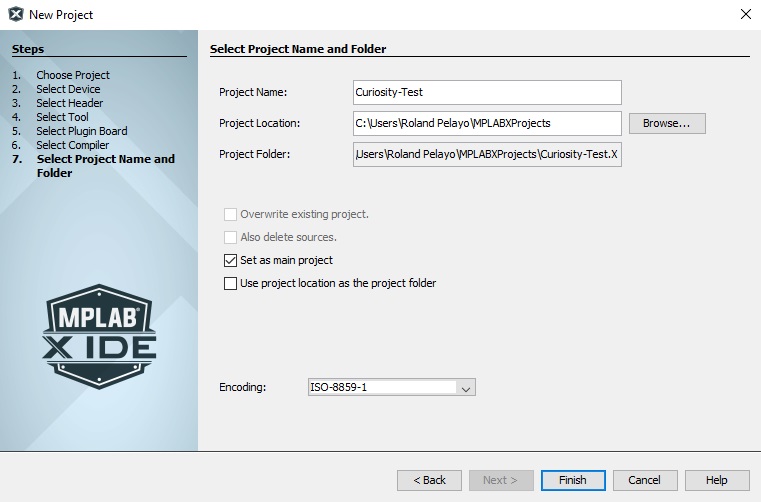
Then I named the project:
Once I’m on the editor, I wrote a code to flash one of the LEDs on the Curiosity board:
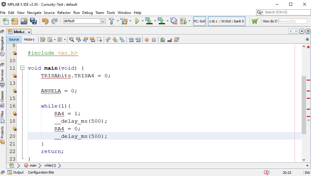
Here’s that code in case you want to try it:
/*
 * File:   blink.c
 * Author: Roland Pelayo
 *
 * Created on February 5, 2019, 4:30 AM
 */
#define _XTAL_FREQ 4000000

#include <xc.h>

void main(void) {
    TRISAbits.TRISA4 = 0;

    ANSELA = 0;

    while(1){
        RA4 = 1;
        __delay_ms(500);
        RA4 = 0;
        __delay_ms(500);
    }
    return;
}
[the_ad id="3059"]
Finally, I compiled and uploaded the code by just pressing the circled button:
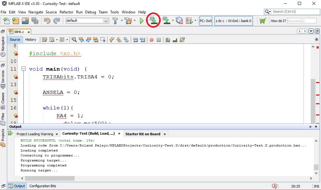
If everything is successful, the LED on the board should now be flashing. It may take a longer time for the program to run for first-time-used Curiosity boards as it needs to download the bootloader and other configuration software.
That's it for my initial use of the Curiosity HPC. On my next article, I’ll be exploring the other parts of the board.
[the_ad id="3059"]

