

Flame sensors are found from the simplest gas stoves to huge industrial plants. There are different types of fire sensors -- some cheap, some expensive. Yet they’re all built for one single purpose: detect fire. In this article, I will guide you on how to build a flame sensor with a few extra bucks and some microcontroller programming knowledge.
What You’ll Need
- Flame sensor module
- Microcontroller (Arduino or NodeMCU ESP8266 or PIC)
- Power source
- Output device (buzzer or smartphone)
Flame Sensor Module
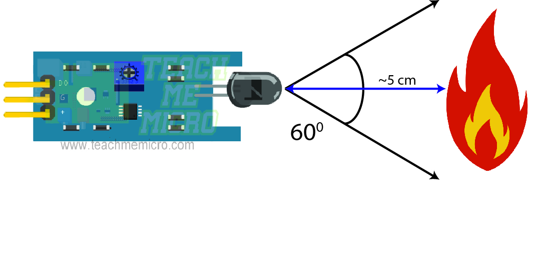
The star of this project is this flame sensor module:

This module contains a phototransistor and signal conditioning electronics. A phototransistor conducts more electrical current when exposed to light. Physics taught us that (visible) light comprises of all colors, from red to violet. By coating the phototransistor with black epoxy, it becomes more sensitive to red or even invisible below red or infrared. Interestingly, flame emits infrared radiation. Thus, when this sensor sees flame, it conducts more current.
Microcontrollers read voltage, not current. Thus, the signal conditioning circuit in the module converts the current into levels of voltage that is considered safe for the microcontroller (typically, the maximum voltage should be the supply voltage to the microcontroller).
The flame sensor module also contains indicator LEDs. One LED lights up (PWR-LED) when the module is powered up while another lights up (D0-LED) when the sensor detects fire.
Moreover, the voltage from the D0 pin falls to zero in the vicinity of fire and rises to the supply voltage when there is none. We use this as a trigger for the microcontroller.
Arduino - Flame Sensor Interface
I aim to use three different kinds of microcontroller for this project. First, I’ll show how to build an Arduino flame sensor with a buzzer as indicator.
Since the module only provides two values, on and off, we don’t need to use any of the analog pins of the Arduino. The wiring diagram below shows that the D0 pin of the module connects to the digital pin 2 of the Arduino UNO:
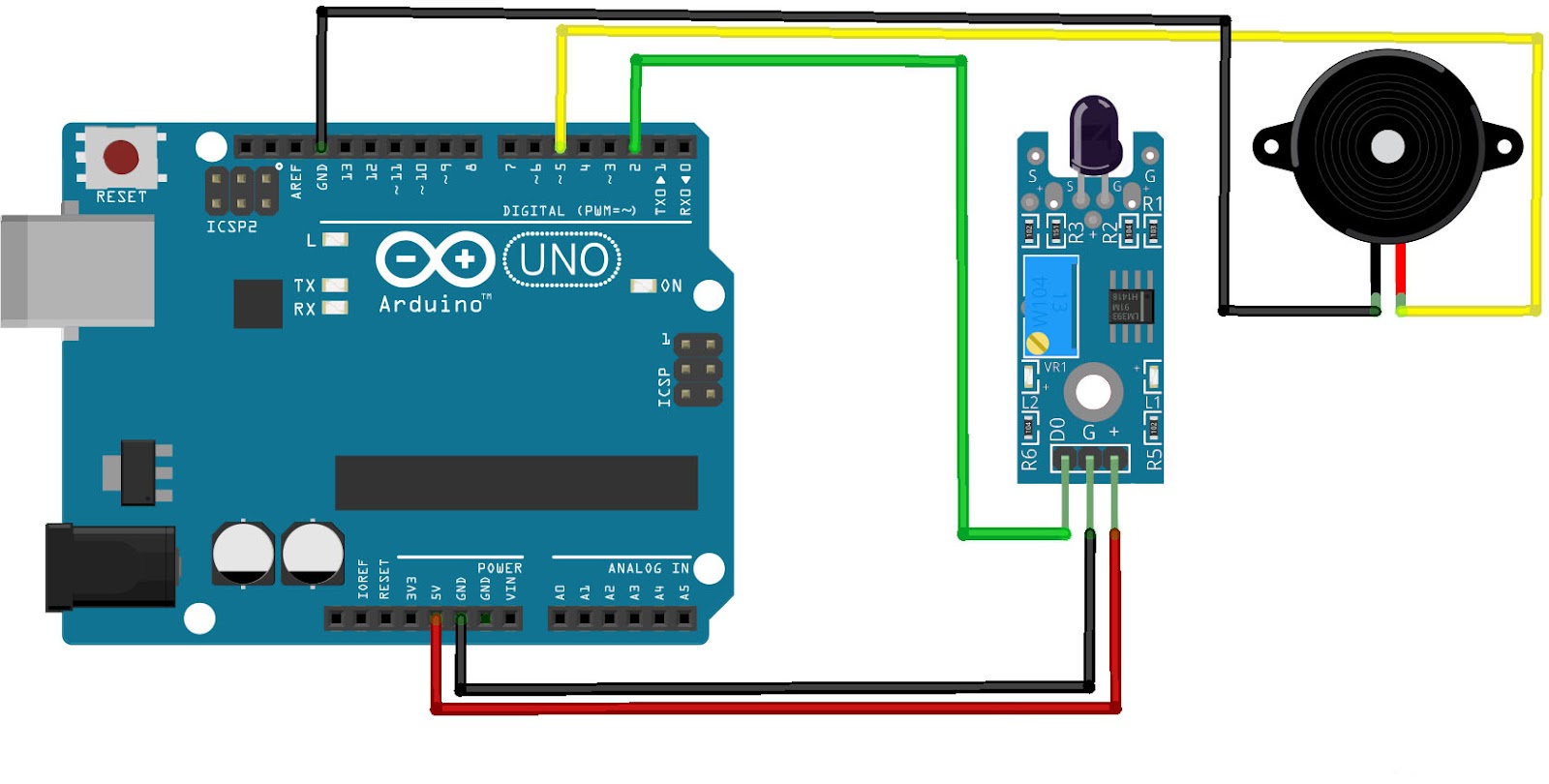
Moreover, the VCC or + pin connects to 5V and the G pin is connected to GND. Note that the fire detector module can also run on 3.3V. Finally, the buzzer’s red wire is connected to pin 5 while its black pin is wired to GND. In this project, I am using a buzzer that can run from voltages 3 to 24 V.
The sketch is straightforward:
const int sensor_pin = 2;
const int buzzer = 5;

void setup() {
  pinMode(sensor_pin,INPUT_PULLUP);
  pinMode(buzzer,OUTPUT);
}

void loop() {
  if(digitalRead(sensor_pin) == LOW){
    digitalWrite(buzzer,HIGH);
  }else{
    digitalWrite(buzzer,LOW);
  }
}
I gave pins 2 and 5 appropriate aliases:
const int sensor_pin = 2;
const int buzzer = 5;
Inside setup(), we declare sensor_pin as an input pin while buzzer is an output pin:
pinMode(sensor_pin,INPUT_PULLUP);
pinMode(buzzer,OUTPUT);
In loop(), we check if the sensor_pin voltage is zero. If it is, we sound the buzzer. If not, then turn off the buzzer.
void loop() {
  if(digitalRead(sensor_pin) == LOW){
    digitalWrite(buzzer,HIGH);
  }else{
    digitalWrite(buzzer,LOW);
  }
}
The fire sensor can detect flame within its 60 degree capture angle. The distance of the flame varies with ambient light. In my tests, the sensor was able to detect a match’s flame from around 5 cm.
Using the Flame Sensor with PIC16F877A
The difference here is that we are using a different microcontroller and thus, a different compiler. Nevertheless, the concept is the same: the PIC16F877A reads the D0 pin and if its low, fire up the buzzer and so on.
Here’s the wiring diagram:

The D0 pin of the fire detector module connects to RB0 while the buzzer’s red wire is connected to RB1.
The C code (XC8) for the circuit above is shown below:
#define _XTAL_FREQ 4000000
#include <xc.h>

void main(void) {

    TRISBbits.TRISB0 = 1;
    TRISBbits.TRISB1 = 0;
    while(1){
        if(PORTBbits.RB0 == 0){
            PORTBbits.RB1 = 1;
        }else{
            PORTBbits.RB1 = 0;
        }
    }
    return;
}
The pin RB0 is an input pin while RB1 is an output pin. Hence their corresponding TRIS bits should be:
TRISBbits.TRISB0 = 1;
TRISBbits.TRISB1 = 0;
We then use simple if-else statements to check if the sensor detects a fire and then turn on or off the buzzer:
while(1){
 if(PORTBbits.RB0 == 0){
    PORTBbits.RB1 = 1;
 }else{ PORTBbits.RB1 = 0;
 }
}
There's no loop() function in XC8 so we create our own infinite loop using the while(1) statement.
That's it for interfacing the flame detector with a PIC microcontroller.
Flame Sensor and ESP8266
Finally we are down to our last microcontroller, the ESP8266. Of course, we will be using the flame sensor with the ESP8266 according to the latter’s capabilities. In this version, the user will receive a push notification on his or her smartphone everytime the fire detector is triggered.
Here’s the wiring diagram:
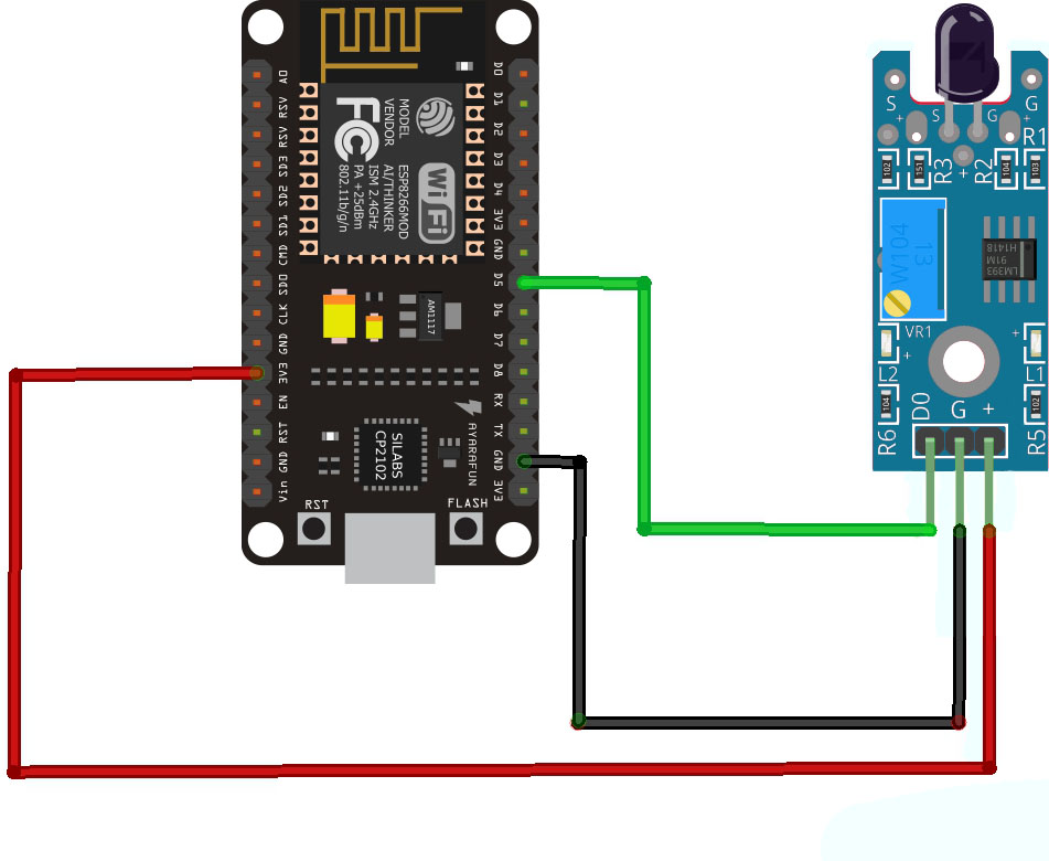
This diagram is the simplest since we don’t need the buzzer anymore. Note that I am using a NodeMCU ESP8266 board for this project. If this is your first time using the NodeMCU, please follow the instructions to program it using the Arduino IDE.
Here is the full sketch:
/*
 *  This sketch sends push notifications via Pushbullet App through PushingBox.
 *
 *  You need to create a service and scenario at pushingbox.com to acquire
 *  a device ID. Also change lines 12 and 13 to your own WiFi SSID and password
 *
 */
#include <ESP8266WiFi.h>
#include <WiFiClient.h>
#include <ESP8266WebServer.h>

const char* ssid     = "<your WiFi SSID>";
const char* password = "<your WiFi password>";

const char* host = "api.pushingbox.com";
const char* devid = "vADAB279A6A4DA5A";

const int sensor_pin = 14;

void setup()
{
    pinMode(sensor_pin,INPUT_PULLUP);
    pinMode(buzzer,OUTPUT);

    Serial.begin(115200);
    delay(10);

    // We start by connecting to a WiFi network

    Serial.println();
    Serial.println();
    Serial.print("Connecting to ");
    Serial.println(ssid);

    WiFi.begin(ssid, password);

    while (WiFi.status() != WL_CONNECTED) {
        delay(500);
        Serial.print(".");
    }

    Serial.println("");
    Serial.println("WiFi connected");
    Serial.println("IP address: ");
    Serial.println(WiFi.localIP());
}

int value = 0;

void loop()
{
    delay(5000);

    if(digitalRead(sensor_pin) == LOW){  //flame sensor triggered

    Serial.print("connecting to ");
    Serial.println(host);

    // Use WiFiClient class to create TCP connections
    WiFiClient client;
    const int httpPort = 80;
    if (!client.connect(host, httpPort)) {
        Serial.println("connection failed");
        return;
    }

    // We now create a URI for the request
    String url = "/pushingbox";
    url += "?devid=";
    url += devid;

    Serial.print("Requesting URL: ");
    Serial.println(url);

    // This will send the request to the server
    client.print(String("GET ") + url + " HTTP/1.1\r\n" +
                 "Host: " + host + "\r\n" +
                 "Connection: close\r\n\r\n");
    unsigned long timeout = millis();
    while (client.available() == 0) {
        if (millis() - timeout > 5000) {
            Serial.println(">>> Client Timeout !");
            client.stop();
            return;
        }
    }

    // Read all the lines of the reply from server and print them to Serial
    while(client.available()) {
        String line = client.readStringUntil('\r');
        Serial.print(line);
    }

    Serial.println();
    Serial.println("closing connection");
    }else{;}
}
Before uploading this sketch, we need to configure Pushingbox and Pushbullet for this project to work.
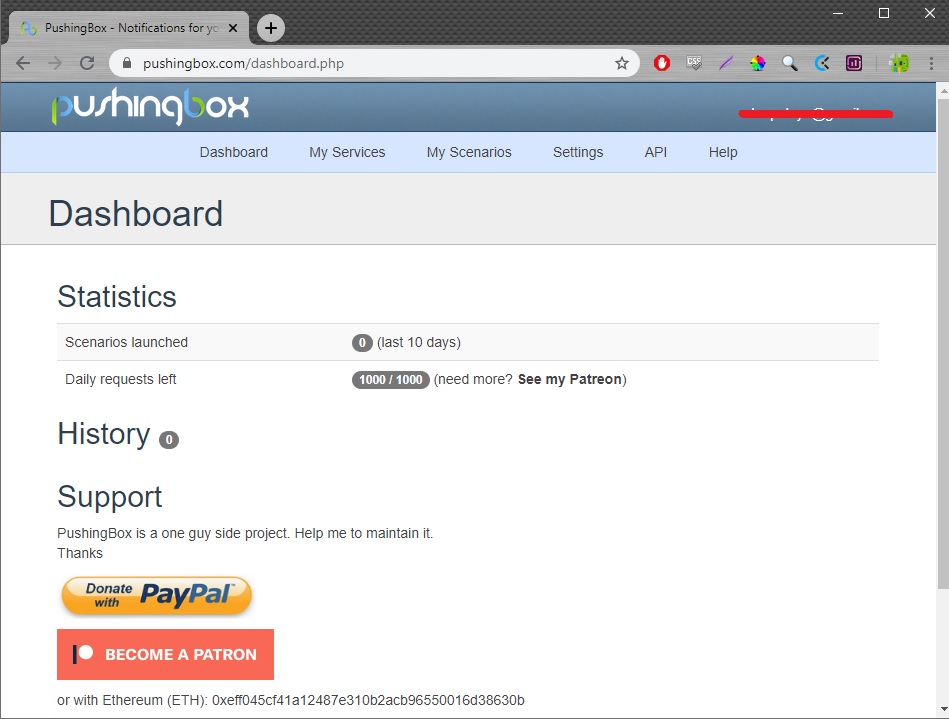
First, go to Pushingbox and signup or login to your account. You will then be redirected to the Dashboard page:
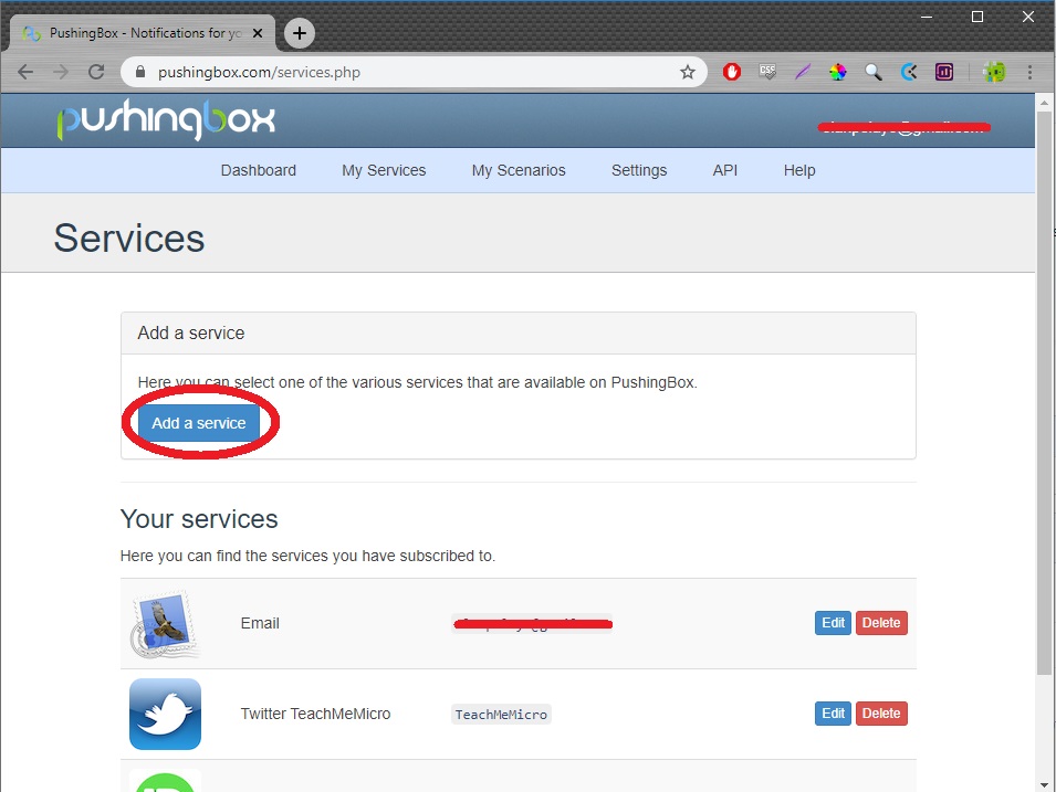
Click the My Services tab and click “Add a service”:
Next, look for the Pushbullet service:
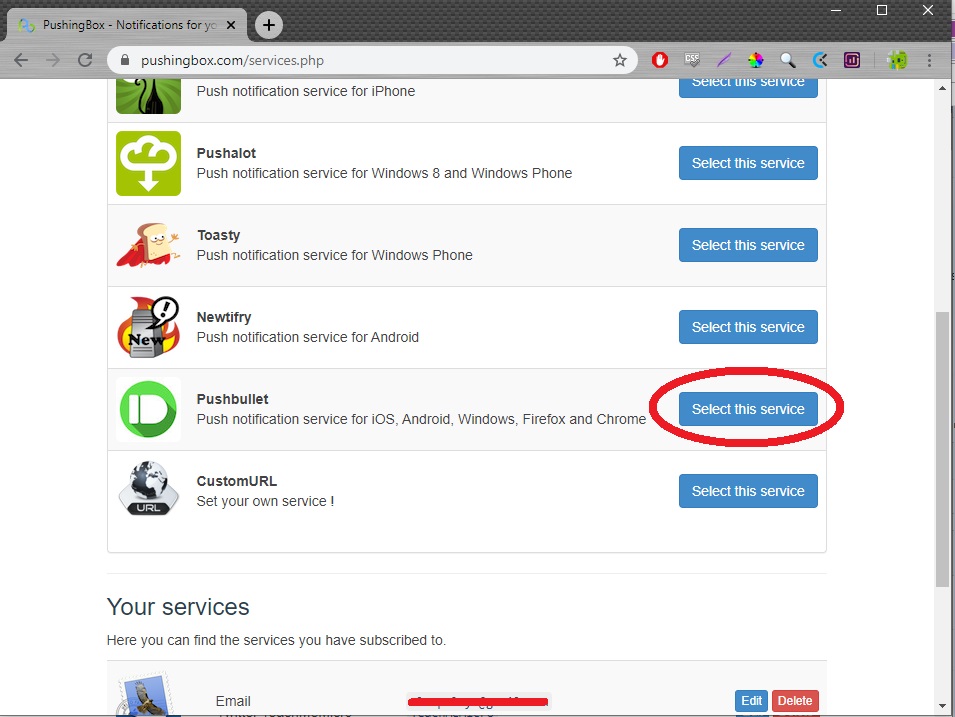
However, before your press the “Select this service” button, you need to have a Pushbullet account first.
Go to Pushbullet:

Sign up or login to your account. After that, find Settings on the dashboard. There you’ll find your access token:

Go back to Pushingbox, click add a service again and this time click the “Select this service” button for pushbullet. A window appears:
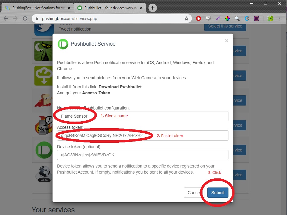
Give the configuration a name, paste your Pushbullet token then click submit.
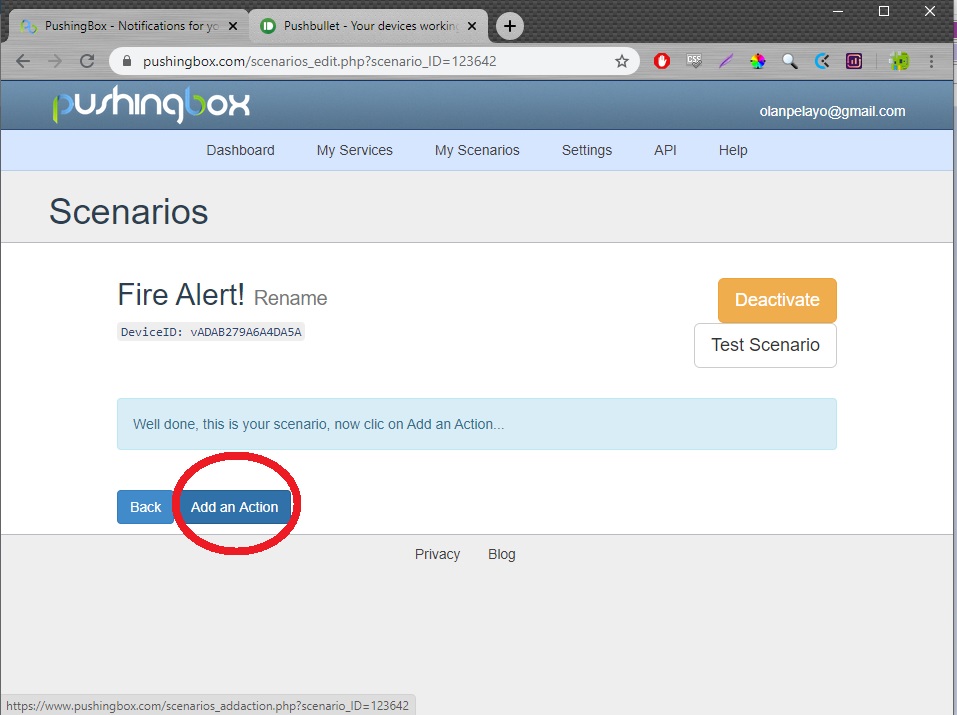
Next, click the My Scenarios tab to add a scenario linked to the service just created:

After creating the scenario, add an action:
Make sure you select the appropriate scenario:

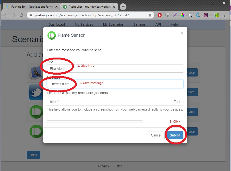
A window appears; give the action title, push notification message and then click submit.
Finally, copy the device ID whose location is shown:

Now on the sketch, locate line 16 and change the device ID:
const char* devid = "vADAB279A6A4DA5A";
Also, don’t forget to provide your own WiFi’s SSID and password on lines 12 and 13:
const char* ssid     = "<your WiFi SSID>";
const char* password = "<your WiFi password>";
Upload the sketch and you're good to go! Now, install the Pushbullet app on your smartphone and login to your account. Everytime the fire detector is triggered, you will receive a push notification!
Conclusion
The flame sensor project here is limited in capture angle and range. However, there's a special module that contains five phototransistors:
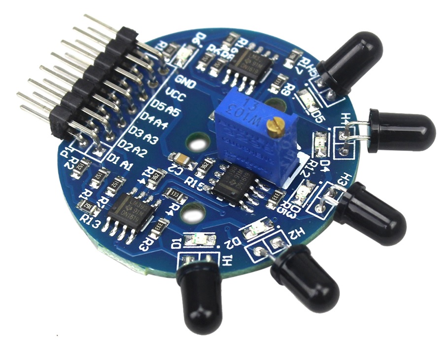 This 5-way fire detector module has a capture angle of 120°. Check prices here.
Hopefully, this article helps you in any way. For any questions, reactions or suggestions, kindly drop comments below.

