
Arduino is easy to use but that's at the expense of numerous features, the most glaring of them is speed. Hence you would rarely see an Arduino in an embedded, industrial setting. ARM Cortex-M microcontrollers are low-cost, energy-efficient 32-bit devices with up to 2 DMIPS/MHz. They are the microcontroller of choice if you are looking into image processing, machine learning, or digital signal processing.
Introduction to Blue Pill
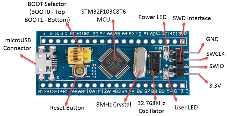
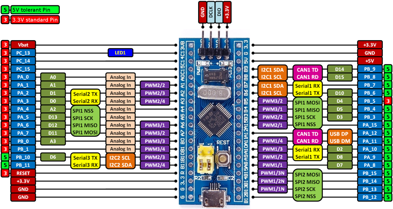
This article features the Blue Pill, a STM32F103C8-powered breakout board. Some notable features of this microcontroller are:
- 1.25 DMIPS/MHz (72 MHz frequency)
- 64 kB of Flash memory
- 20 kb of RAM
- 37 I/O Ports
- 2 x 12-bit ADC with 10 channels each
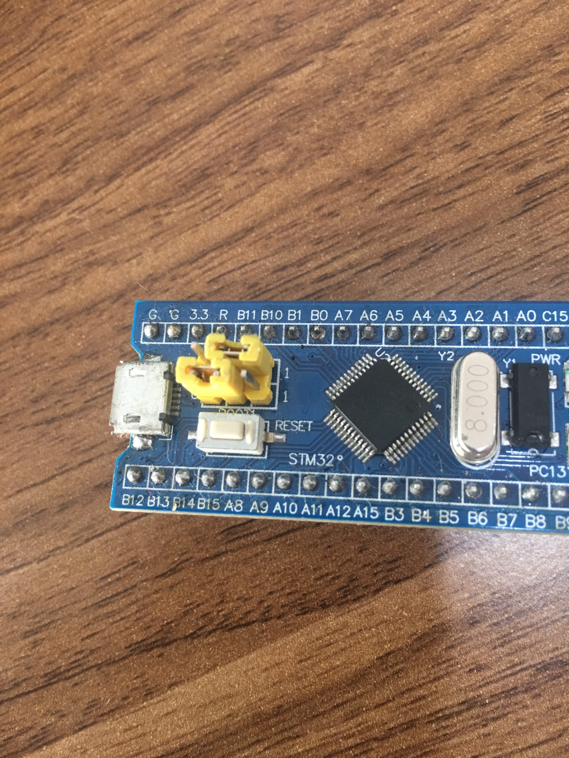
The Blue Pill is designed to be similar to the Arduino Nano with 32 of the 37 I/O ports readily accessible. It can draw power from the microUSB port or the 3.3 V pins. It also has two on-board LEDs, BOOT jumpers, a SWD connector and a reset button.

You can program the Blue Pill using the Arduino IDE, just like how you can program the ESP8266 and ESP32 breakout boards. That will be for a separate tutorial as we will be using STM32's own development platform, the STM32Cube.
Setting Up STM32Cube
To start, download and install STM32Cube.
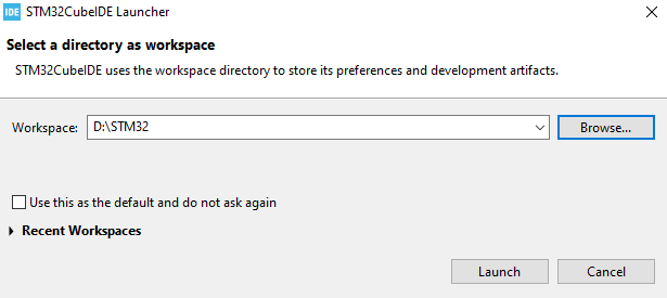
Open STM32Cube then select a location for your workspace. Ticking the check box will skip this window on the next launch.
Next, select the startup project type:
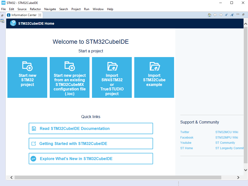
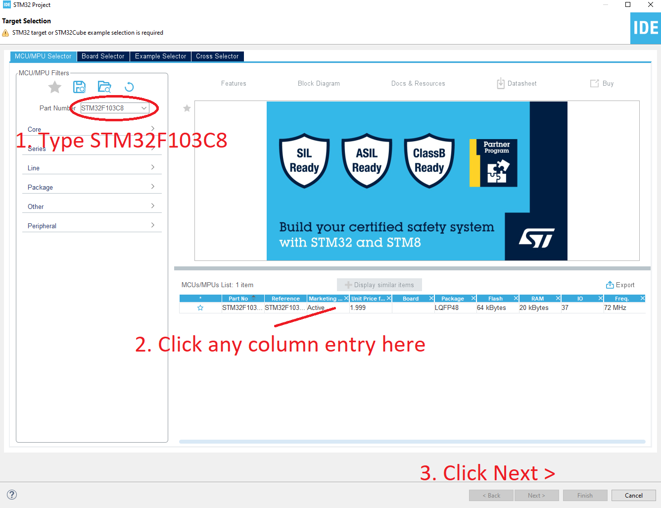
For first-time users, choose "Start new STM32 project". The Device Selection window then appears:
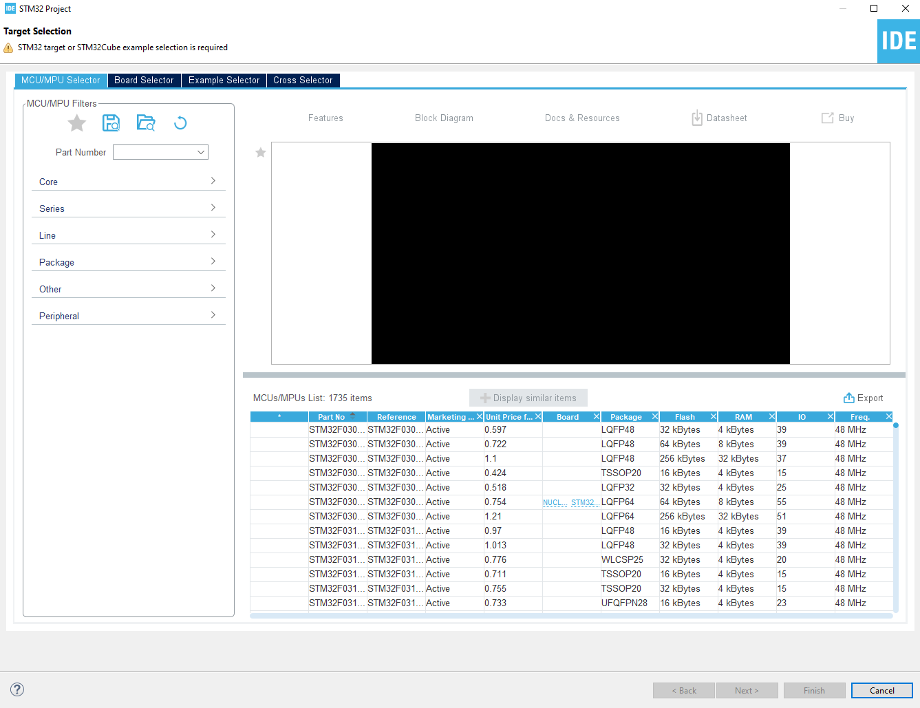
We type in our device, the STM32F103C8, and proceed:
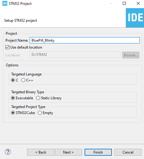
Next, give the project a name. Here I named it BluePill_Blinky:
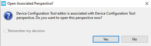
A pop-up window opens that asks you to open associated perspective. Click Yes:
You should now be on the Device Configuration Tool window. Here you can configure the function of each of the pins of the STM32F103C8. This is a really neat feature of STM32Cube as it makes setting up your project faster and easier.
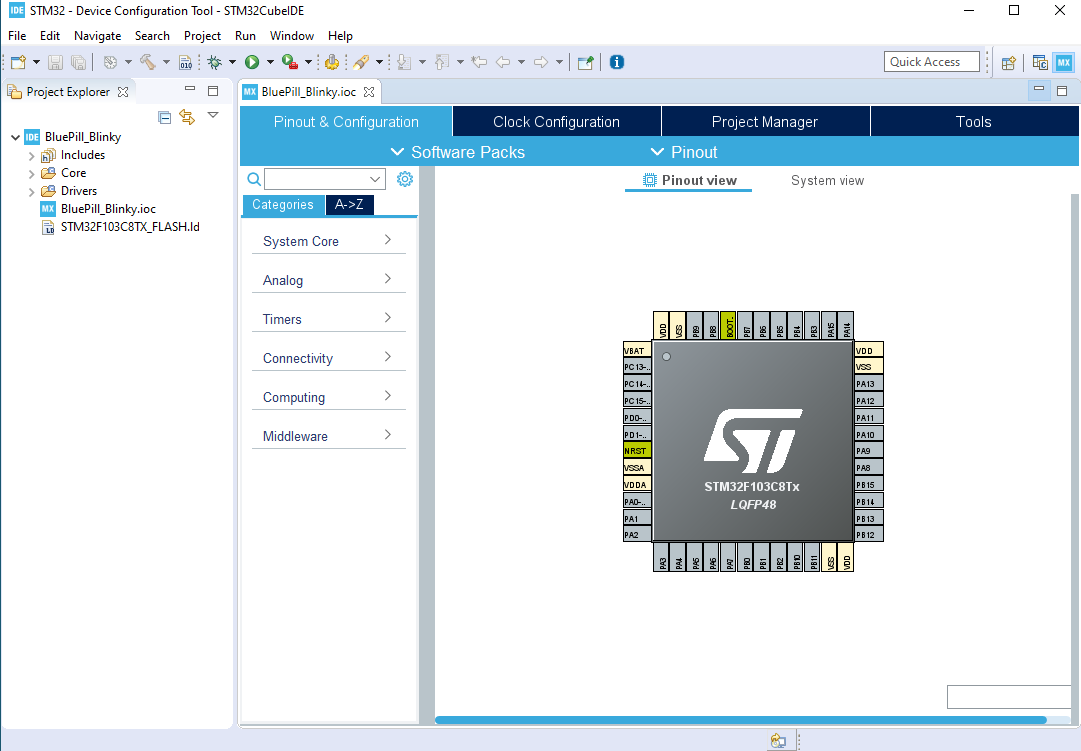
Our example project is an on-board LED flasher. In the Blue Pill you can see one of the LEDs with a label PC13. This means it's wired directly to pin PC13.
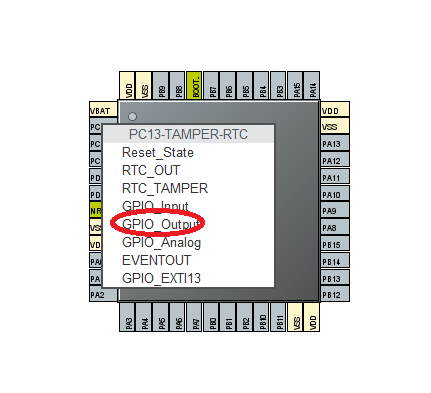
Click on the PC13 pin on the Device Configuration Tool. A menu appears with all the possible functions of the pin. Since we're just flashing a LED, we make PC13 a GPIO_Output pin.
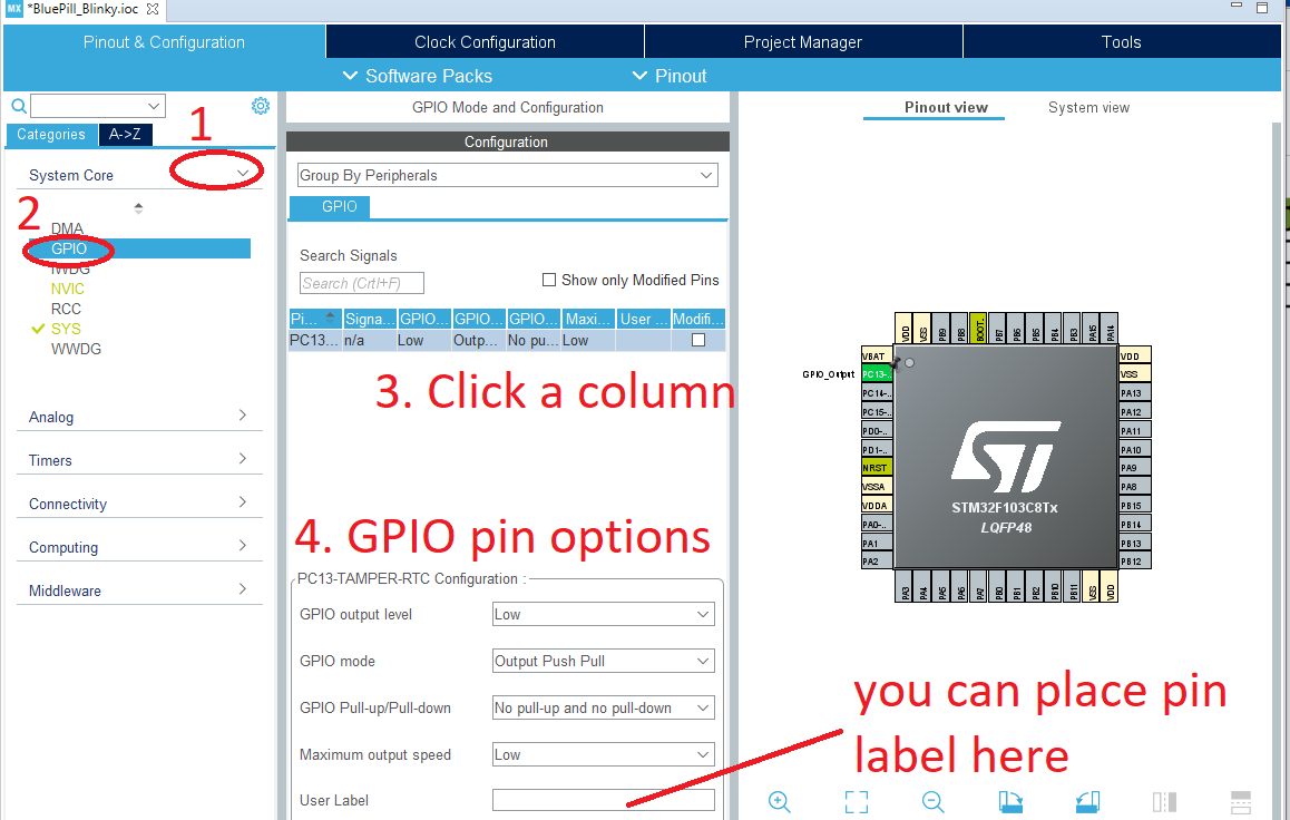
We can view more options for the PC13 pin by expanding System Core and then choosing GPIO. Here we can configure the initial state of PC13, its mode, pull-up/pull-down resistors and label.
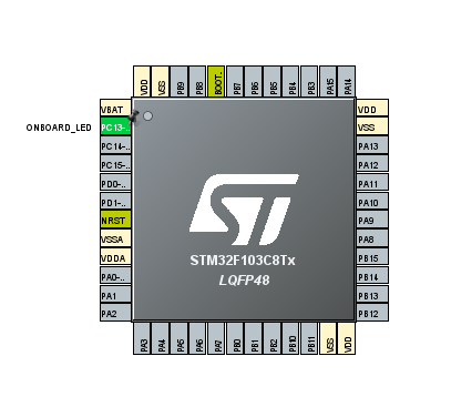
Here, I gave PC13 a label "ONBOARD_LED":
After this, go to File -> Save (or CTRL+S). A message window appears.
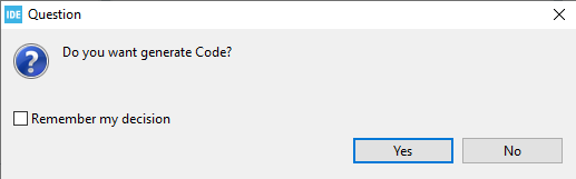
If you click Yes, a template code will be generated with all the configurations already there. A really great feature!
Another message window appears, this time asking you to open a perspective:
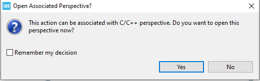
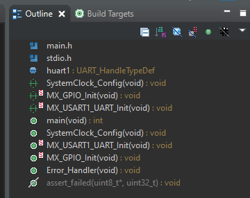
Answering yes to this message will insert a pane on the right side which shows an outline of the code:
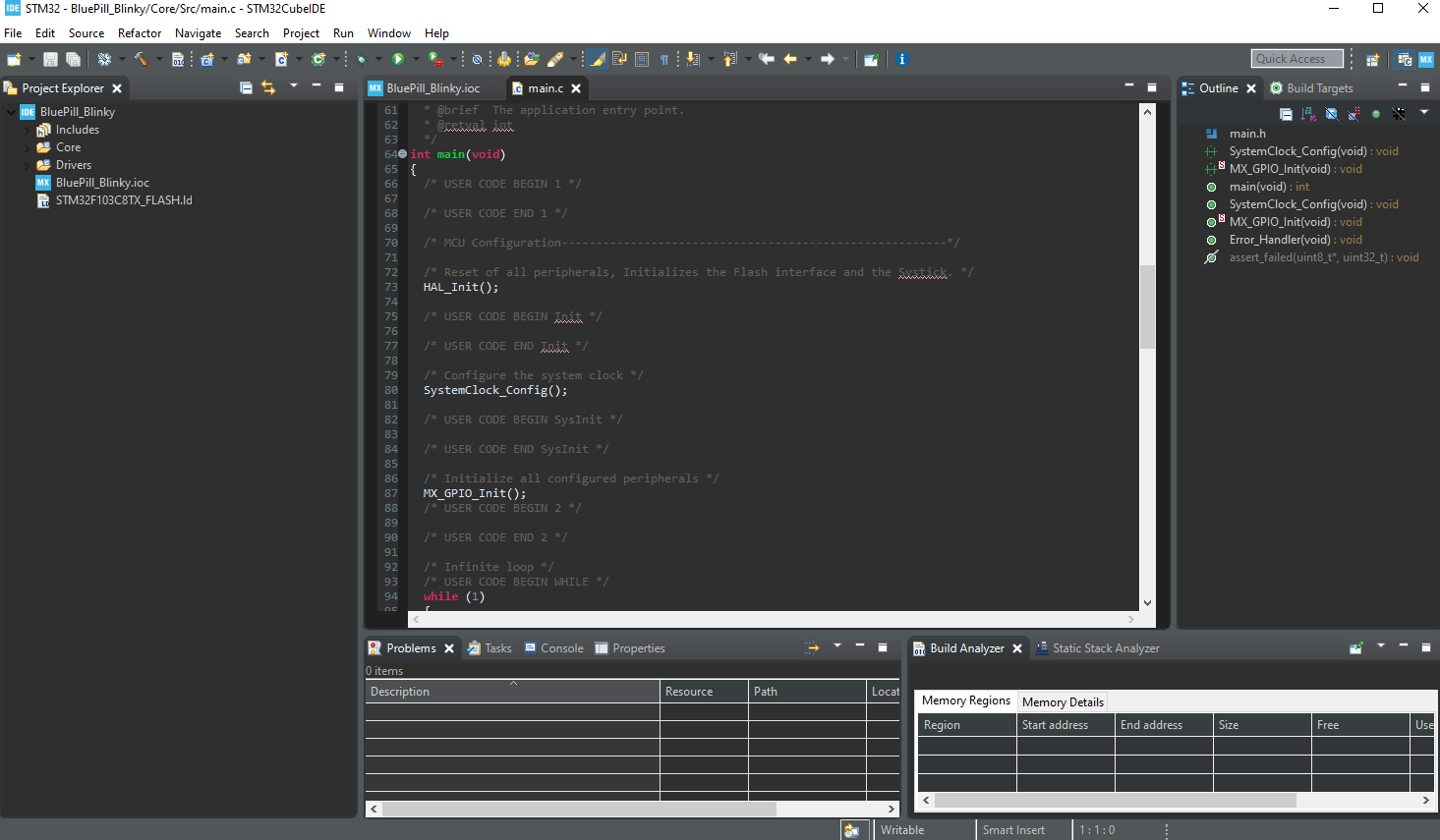
That's it! You will now see your main.c. file on the IDE. On the left is the Project Explorer pane where you can view all the project files. If you want to view the Device Configuration Tool again, just click the one with an .ioc extension.
Building the Blinky Code
We will now insert some lines in the main.c file in order to flash the on-board LED. First, look for a while(1) loop inside the main() function. This is the part that executes infinitely while the microcontroller is on. This loop should have the following lines of code for flashing the on-board LED:
  /* Infinite loop */
  /* USER CODE BEGIN WHILE */
  while (1)
  {
    /* USER CODE END WHILE */
	  HAL_GPIO_WritePin(ONBOARD_LED_GPIO_Port, ONBOARD_LED_Pin, GPIO_PIN_RESET);
	  delay(500000);
	  HAL_GPIO_WritePin(ONBOARD_LED_GPIO_Port, ONBOARD_LED_Pin, GPIO_PIN_SET);
	  delay(500000);

    /* USER CODE BEGIN 3 */
  }
  /* USER CODE END 3 */
The HAL_GPIO_WritePin() function makes a pin high or low. Its parameters are the I/O Port, the name of the pin and the state of that pin. This line makes the pin high:
HAL_GPIO_WritePin(ONBOARD_LED_GPIO_Port, ONBOARD_LED_Pin, GPIO_PIN_SET);
While this line makes the pin low:
HAL_GPIO_WritePin(ONBOARD_LED_GPIO_Port, ONBOARD_LED_Pin, GPIO_PIN_RESET);
Note that the configurations for the GPIO are in the function MX_GPIO_Init() which was auto-inserted by the Device Configuration Tool.
You notice that we have a delay() function between the set and resetting of the pin state. This ensures that our eyes can catch the flashing. However, this is not a built-in function. We insert this function right after the last function Error_Handler():
void delay (int a)
{
  volatile int i,j;
  for (i=0 ; i < a ; i++)
  {
     j++;
  }
  return;
}
A prototype of this function should also be added along with the other generated prototypes:
void SystemClock_Config(void);
static void MX_GPIO_Init(void);
void delay (int a);
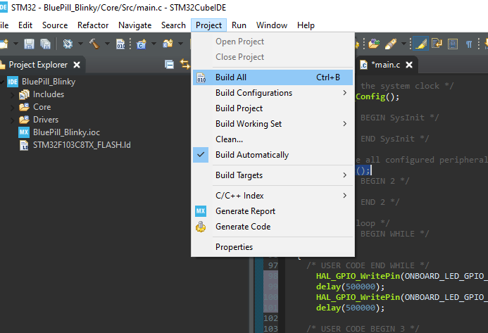
After this, the project is ready for building. Go to Project > Build All (or Ctrl+B):
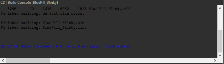
If there's no error, you should see this message at the bottom panel:
Next we'll be sending the code to our Blue Pill. Connect the ST-Link programmer to the Blue Pill board:

Then make sure the BOOT0 jumper is on the right. This makes the Blue Pill enter programming mode.
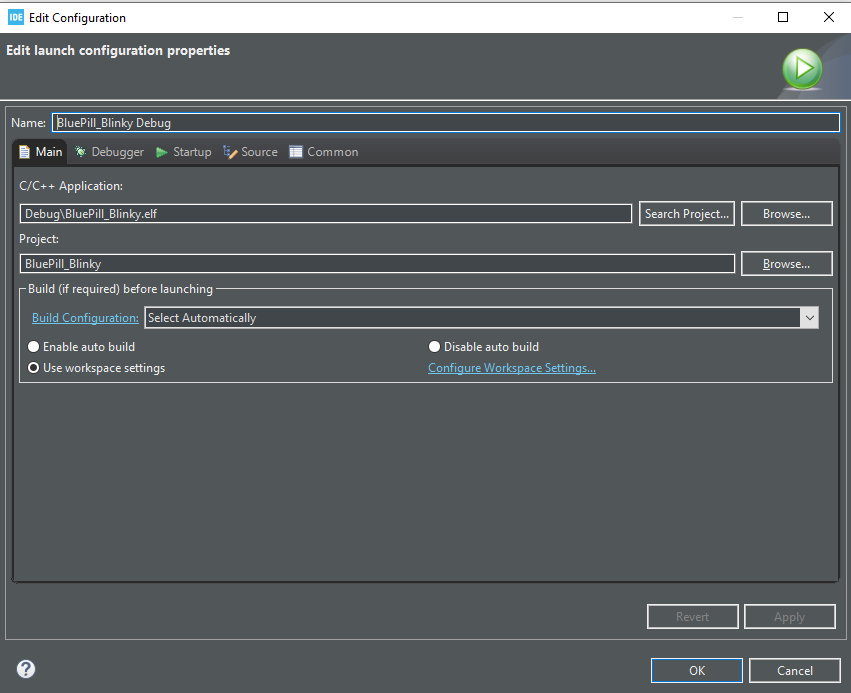
Click the Run button. The launch config window appears. Just click OK.
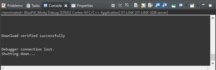
If the code has been successfully sent to the device, the console message is like below:
If the code download fails, press the reset button on the board and try again.
Bring the BOOT0 back to its original position to go back to normal operation mode. Press the reset button and the on-board LED should now be flashing.

