
Measuring an object’s weight can sometimes be part of a bigger project. And unless you have a good reason, you wouldn’t want to use an analog weighing scale. A digital weight sensor is easier to interface with, not to mention its accuracy and durability against an analog weight sensor. In this article, I will show you how to build your own weighing scale using a load cell, HX711 and Arduino.
What is a Load Cell?
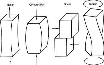
A load cell is a transducer that converts a physical quantity into an electrical signal. The physical quantity here is mechanical force of which there are different types: shear, torsion, tension or compression.
Load cells can be pneumatic (gas), hydraulic (liquid) or resistive (strain gauge). Since this is about Arduino interfacing, we will focus on the resistive load cell.
Strain Gauge Basics
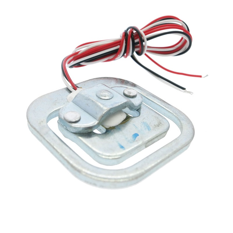
The resistive load cell contains a strain gauge - a sensor that changes its resistance when subject to force. They are often very small and looks like this:
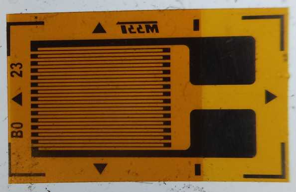
The orange part in this picture is an insulator while the coil pattern is a conductor. With an adhesive, the sensor attaches to the body where the force is applied. Wires is then attached to the large pad to read the resistance of the strain gauge.
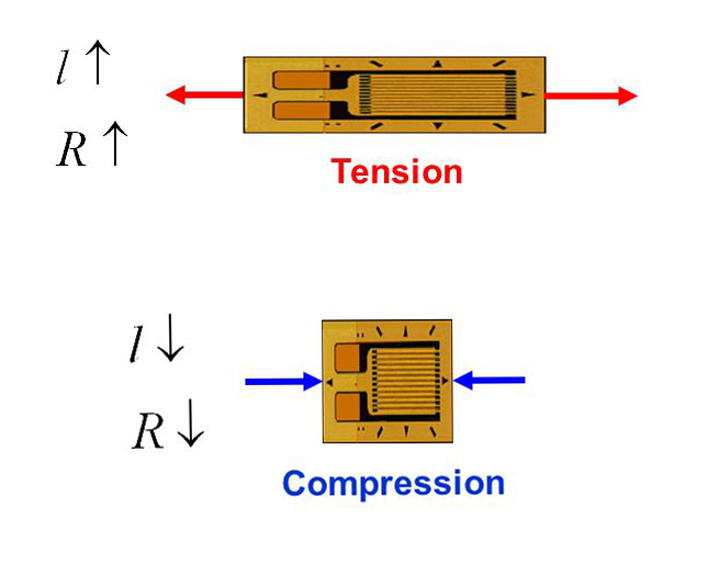
When the body where it’s attached elongates or compresses due to force, the strain gauge also elongates or compresses. The resistance of the strain gauge increases as it elongates and decreases as it compresses.
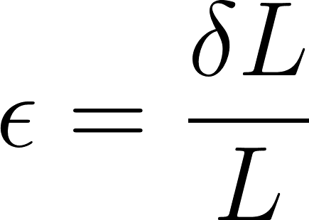
Strain (or more correctly engineering strain) is the ratio an object’s change in length to its original length:
Elongation or compression of an object results in strain. For a strain gauge, the strain relates to resistance through its sensitivity or Gauge Factor:
![]()
Here, ΔR is the change in resistance of the strain gauge as the strain ε is applied. RG is the resistance of the strain gauge at no applied strain (nominal resistance).
The sensitivity depends on the type of material. The most common strain gauge is one where the conductor is nichrome. This type has a Gauge Factor of 2.1.
Wheatstone Bridge
Strain gauges in load cells are very small: around 4 to 12 mm. Thus, their strain values and change in resistance is also very small. This change will be very hard for a computing element, say, a microcontroller to detect.
The solution is to use a Wheatstone bridge:
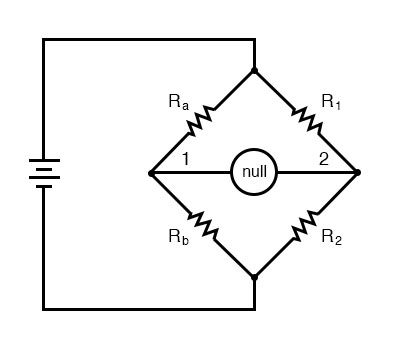
A Wheatstone bridge’s purpose is to detect very small changes in resistance in one of its arms. We can replace the resistors in this circuit with strain gauges. If the strain gauges have the same nominal values, then no current flows through the center of the bridge. This is known as balancing the bridge.
If any of the strain gauges experiences strain, their resistance changes. This will unbalance the bridge and voltage is now present between nodes 1 and 2. The value of that voltage can be computed as:

The Single Strain Gauge Load Cell
Strain gauge load cells can have one or four strain gauges. This type is a single-strain-gauge load cell:
This type is the same ones on bathroom weighing scales. It is wired same as a voltage divider circuit:
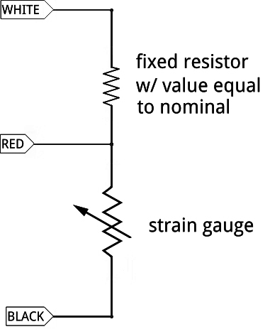
When the variable resistor in this circuit changes, the voltage on the RED wire also changes. However, a voltage divider circuit is not as sensitive to resistance changes as a Wheatstone bridge. You still can use this with a bridge though, but you would need four of these.
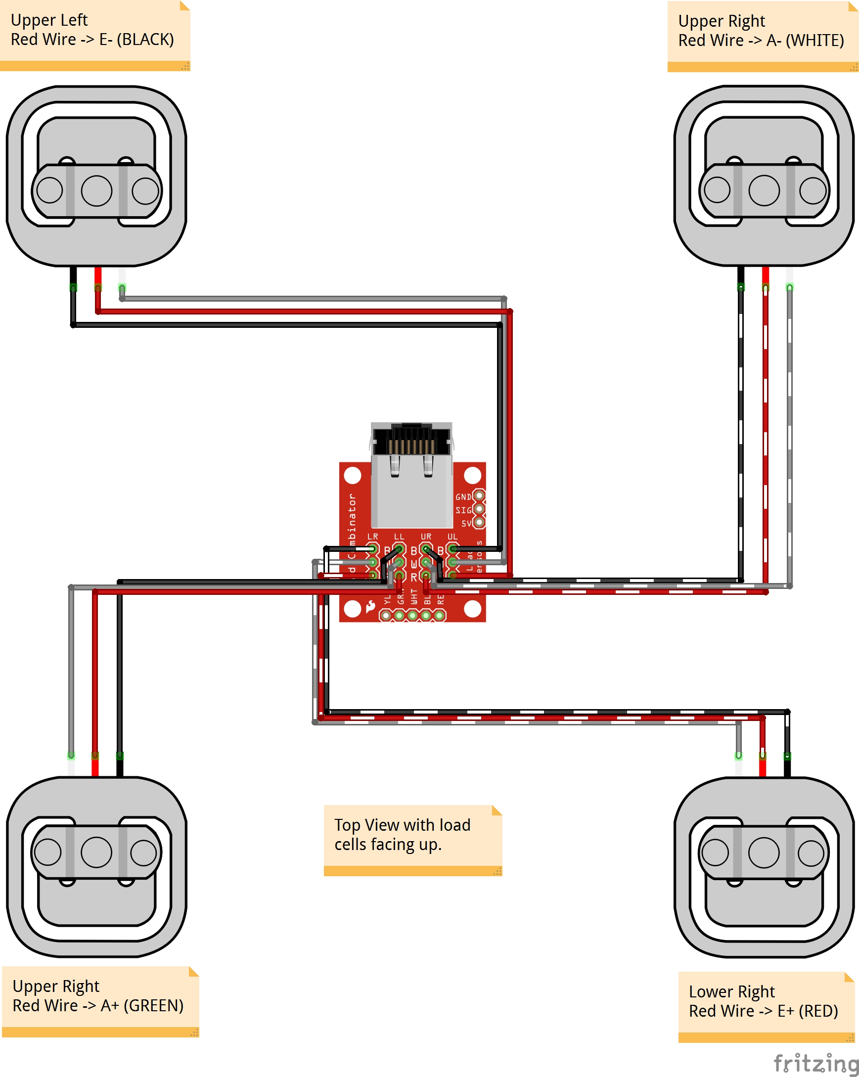
Image from Sparkfun
Bar Load Cells
A bar load cell contain four strain gauges already in a Wheatstone bridge.
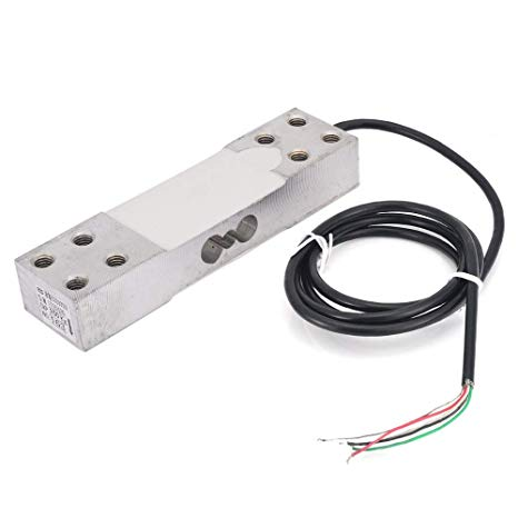
You can buy different versions of the bar load cell. Mine is the the 5 kg version, which means the maximum weight it can handle is 5 kg.
The white blobs on top and bottom have two strain gauges each. The object to be weighed is placed on the edge of the bar (the one far from the wire). This elongates the strain gauges at top and compresses the ones at the bottom.
Bar load cells have four wires, corresponding to four points on the bridge: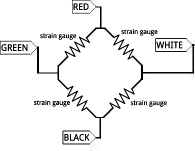
If the load cell has weight, a voltage will exist in the white and green wires. Then again, due to infinitesimal change in the resistance, this voltage is still very small to be read by a microcontroller. This is where the HX711 comes in.
HX711 Load Cell Signal Conditioner
The HX711 is a product of Avia Semiconductors, a company based on Xiamen China.
It is an analog-to-digital converter made specifically for weighing scales. Come to think of it, the Arduino already has its own ADC. However, Arduino’s ADC can only read changes in voltage as small as 4.88 mV. This resolution is calculated using:
![]()
In contrast, the HX711 has a resolution of:

This means it can detect changes as small as 0.298 uV!
Like most Arduino-compatible ICs, a breakout board for HX711 is readily available:
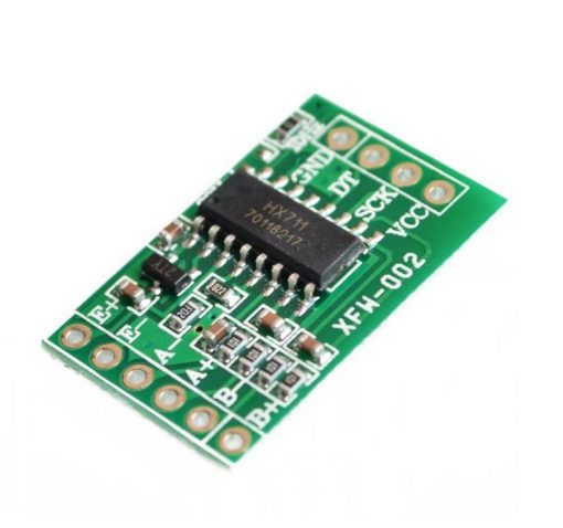
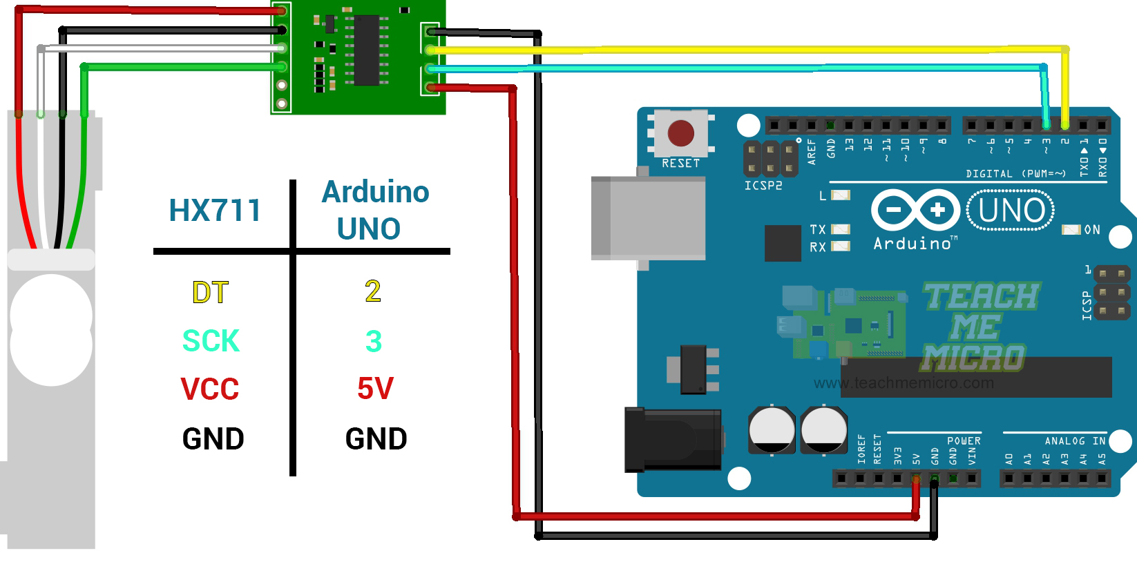
To use the HX711 with the bar load cell, we just connect the output wires White and Green to the A+ and A- pins. Then, we supply power or excitation to the bridge by connecting the Red and Black wires to the E+ and E- pins respectively:
Notice that there is a B+ and B- pins on the HX711. This is for connecting a second Wheatstone bridge to it.
Load Cell Arduino Program
The HX711 communicates to microcontrollers using synchronous serial communication. To start coding, download the HX711 library by Bogdan Necula and Andreas Motl. You can acquire this library by searching through Sketch > Include Library > Manage Libraries in the Arduino IDE:
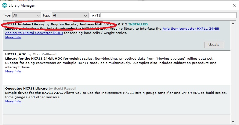
Or you can download this library in this repository.
This library contains several examples. Here's the HX711_basic_example sketch:
#include "HX711.h"

// HX711 circuit wiring
const int LOADCELL_DOUT_PIN = 2;
const int LOADCELL_SCK_PIN = 3;

HX711 scale;

void setup() {
  Serial.begin(57600);
  scale.begin(LOADCELL_DOUT_PIN, LOADCELL_SCK_PIN);
}

void loop() {
  if (scale.is_ready()) {
    long reading = scale.read();
    Serial.print("HX711 reading: ");
    Serial.println(reading);
  } else {
    Serial.println("HX711 not found.");
  }
delay(1000);
}
This example prints the digitized output from the load cell to the serial monitor.
Take note of these lines:
// HX711 circuit wiring
const int LOADCELL_DOUT_PIN = 2;
const int LOADCELL_SCK_PIN = 3;
This indicates where the DT and SCK pins of the HX711 connect to your Arduino.
An HX711 class initializes like this:
HX711 scale;
Then, you can start using the class functions starting with this inside setup():
scale.begin(LOADCELL_DOUT_PIN, LOADCELL_SCK_PIN);
The scale.ready() function returns TRUE if the HX711 is now sending data. Then you can read the data using:
long reading = scale.read();
A long data type because the function returns any number between 0 to 16,777,216! (2 raise to 24).
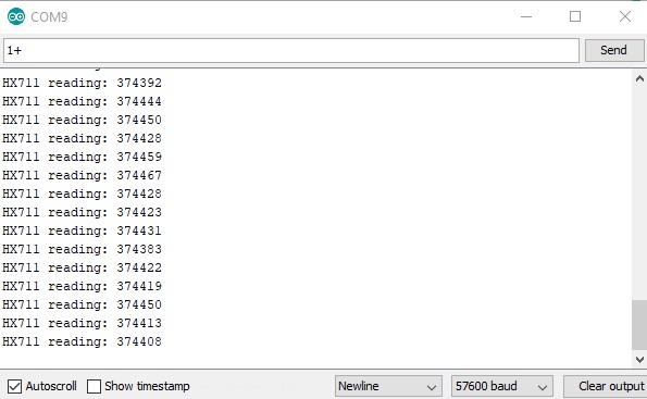
Upload the sketch then open the serial monitor at 57600 baud to see the data.
Testing and Calibration
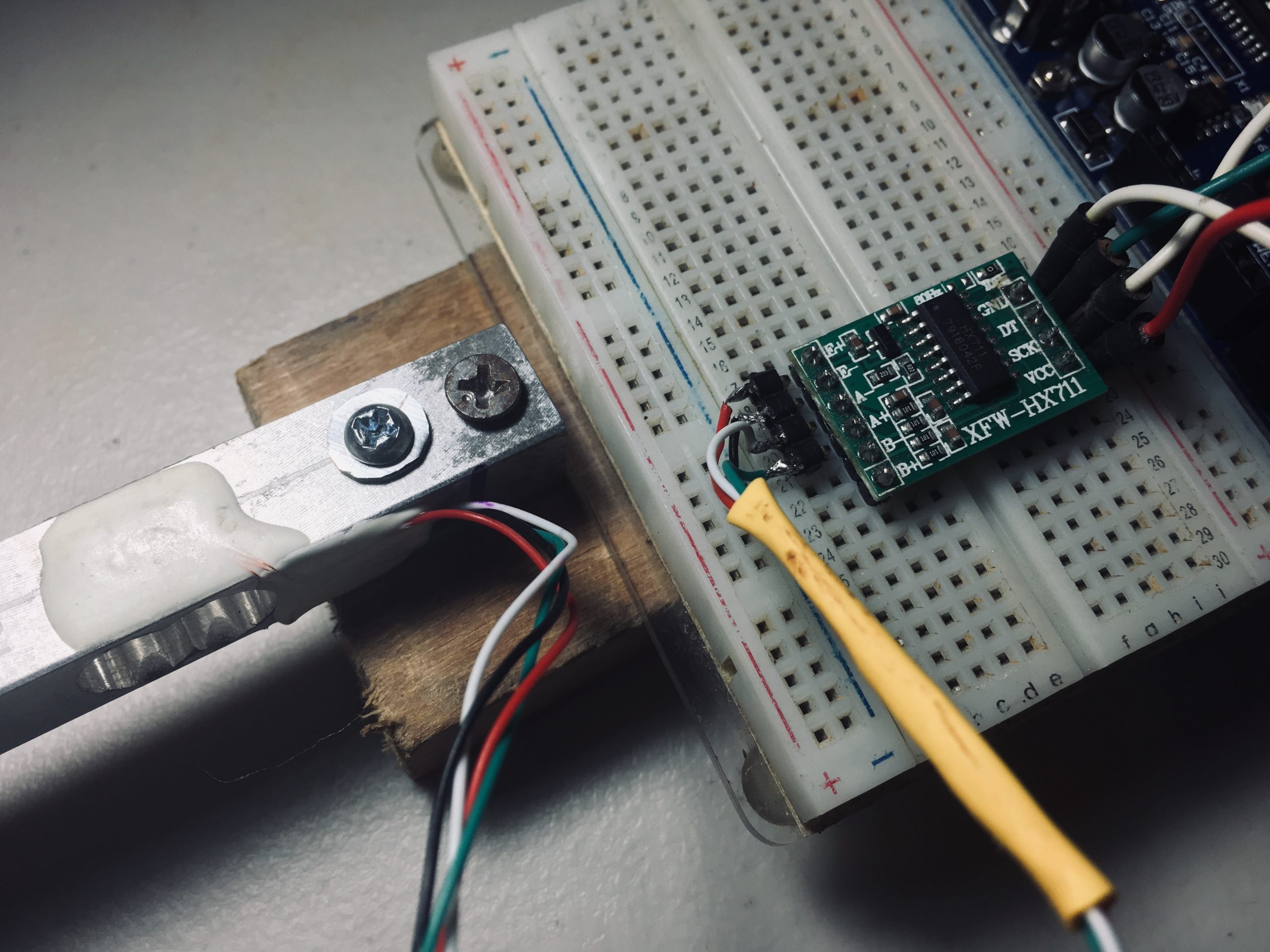
I attached my bar load cell to a wood block as shown:
This is by far the simplest setup that is able to bend the bar and apply strain to the strain gauges. You can try different setups that suit your actual project.
Pushing the edge of the load cell changes the numbers on the serial monitor. These numbers don’t mean anything though unless we calibrate the load cell with the help of known weights.
First, I note the serial monitor values when nothing was on the load cell.
Then, I use some household items and weighed them using a commercial weighing scale. This is a can of corned beef and it weighs 250 g:
Next, I mount the can to the load cell then use the hx711_basic_example sketch to read the data from the HX711.
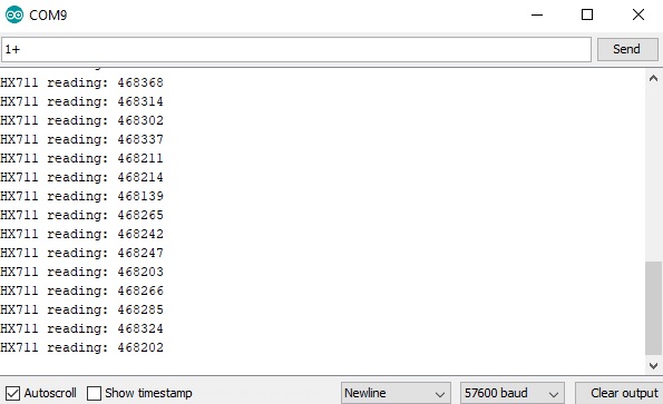
Then using a rough average of these values, I use the two-point form of the linear equation to derive a formula:
![]()
![]()
In this equation, y is the unknown weight in grams while x is the value from the scale.read() function.
Here is now a sketch that displays the weight in grams:
#include "HX711.h"

// HX711 circuit wiring
const int LOADCELL_DOUT_PIN = 2;
const int LOADCELL_SCK_PIN = 3;

HX711 scale;

void setup() {
  Serial.begin(57600);
  scale.begin(LOADCELL_DOUT_PIN, LOADCELL_SCK_PIN);
}

void loop() {

  if (scale.is_ready()) {
    long reading = scale.read() * 266;
    float grams = (float)reading / 100000.0;
    grams = grams - 996.0;
    Serial.print("HX711 reading: ");
    Serial.print(grams);
    Serial.println(" g");
  } else {
    Serial.println("HX711 not found.");
  }

  delay(1000);

}
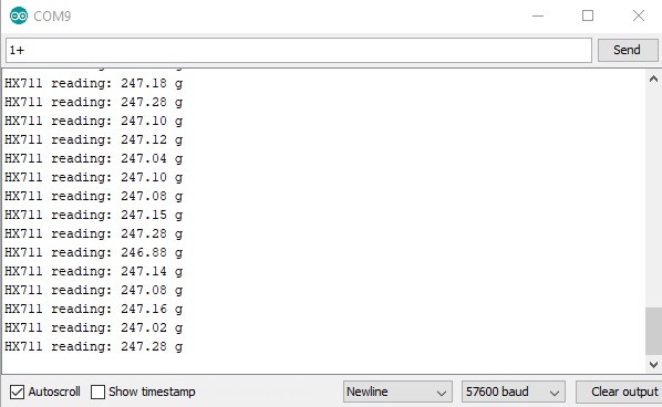
And this is what the serial monitor shows:
Final Words
Clearly the output is not 100% accurate and needs fine tuning. Thankfully, the error is consistent so I may just add 3 g to my formula to get to 250 g.
If you've reached this far, thanks for reading! Hopefully, you follow the procedure I outlined in calibrating the load cell and not just copy the last sketch I gave. This is because your load cell might give different values than mine.
For any suggestions, reactions or questions about this tutorial, kindly drop a comment below.

