
For most microcontrollers, the input and output channels are handled by data direction special function registers. AVR microcontrollers call them Data Direction Registers (DDR) while ARM-based STM32 has a group of “GPIO” registers. PICs call them TRIS registers which is supposed to be short for “TRIState”. In this article, we will look at how to manipulate the pins of the PIC16F84A microcontroller using the TRIS register.
Why TRIState?
A microcontroller’s pins can have three state: input, output or floating. If you want to connect an LED to a pin, you need to set that pin as an output. If you need to use a button, you set the button pin as input. A floating pin is a pin which has not been defined as either input or output. Generally, we don’t use floating pins with PICs.
To set a pin as input, we set its corresponding TRIS bit. For example, if we want to set all PORTB’s as input then the ASM code below does the job:
MOVLW b’11111111’
MOVWF TRISB
Clearing the pin does the opposite. So if you want to set PORTA.0 as an output then do this:
BCF TRISA, 0
Of course, the examples above are some of the few ways to set and clear bits on a register using PIC ASM. I suggest you go read assembly language for PICs if you need a refresher.
The PIC16F84A has 5 PORTA pins and 8 PORTB pins. All PORTB pins can be set as either input or output. You can do the same for the 4 pins on PORTA with the exception of PORTA.4, which can only sink current and not source it. This means it can be only set as input. As to why is that, I am not entirely sure. But I know that PORTA.4 has a secondary function of reading clock pulses.
Simple Input/Output Assembly Program
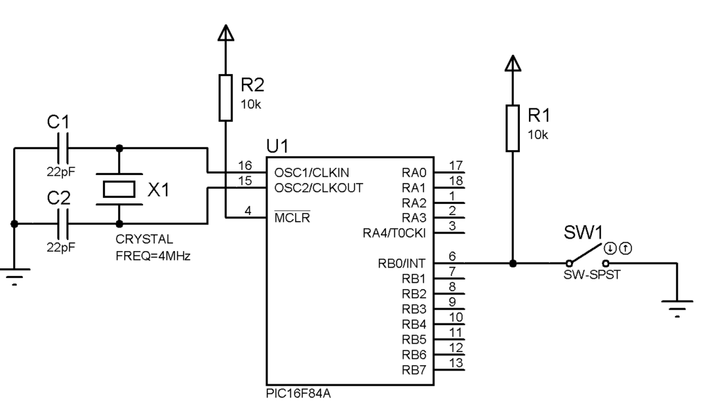
Let’s do a simple program. A LED is connected to PORTA,0 while a switch is attached to PORTB,0. The LED should turn on when the switch is on, and turn off when the switch is off.
The circuit for this code should look like this:
; TODO INSERT CONFIG CODE HERE USING CONFIG BITS GENERATOR
#INCLUDE

RES_VECT  CODE    0x0000            ; processor reset vector
    GOTO    START                   ; go to beginning of program

; TODO ADD INTERRUPTS HERE IF USED

CBLOCK 0x0C
    COUNT1
    COUNT2
ENDC


MAIN_PROG CODE                      ; let linker place main program

 START
    BSF STATUS, RP0
    CLRF TRISA
    MOVLW 0xFF
    MOVWF TRISB
    BCF TRISB, 0
    BCF STATUS, RP0

 MAIN
    BCF PORTA,0
    BTFSS PORTB,0
    GOTO on
    GOTO MAIN
    BSF PORTA,0
    CALL DELAY
    GOTO main

 DELAY
    LOOP1 DECFSZ COUNT1, 1
    GOTO LOOP1
    DECFSZ COUNT2,1
    GOTO LOOP1
    RETURN

    END
On the start routine, we begin with shifting to bank 1 since the TRIS registers are found there. This is done by setting bit RP0 on the STATUS register. Then we write the corresponding literals to the TRIS registers. After that, we shift back to bank 0 (line 16).
The main routine checks if PORTB.0 is set or cleared using the BTFSS op-code. If that pin is set (switch off), line 20 is skipped and the program will do an endless loop. Thus, the LED stays off. Otherwise, the program will jump to the on label and sets PORTA.0. A delay is introduced for stability and the program checks the status of PORTB.0 again.
Input/Output using C
The above ASM code can be implemented in XC8 like this:
#define _XTAL_FREQ 4000000
#include <xc.h>


void main(void) {
    TRISB = 0x01;               // Initialize PORTB0 as all input
    TRISA = 0x01;               // Initialize All PORTA as output
    while(1){
        if(RB0 == 0){
            PORTA = 0b00000001;    // Set RA0
        }else{
            PORTA = 0b00000000;    // Clear RA0
        }
    }
}
A Simple Challenge
Modify the code above so that another LED is attached to PORTA.1. When the switch is turned on, PORTA.0 LED lights up while PORTA.1 LED turns off. Conversely, PORTA.0 LED turns off and PORTA.1 LED lights up when switch is turned off.
On the next part of this tutorial, we will look at a new way to code PICs.

