

The NodeMCU is a development board featuring the popular ESP8266 WiFi chip. As it turns out, you can program the ESP8266 just like any other microcontroller. Its obvious advantage over the Arduino or PIC is that it can readily connect to the Internet via WiFi. However, the ESP8266 breakout board has limited pins although the chip itself has a lot of output ports. The NodeMCU solves this problem by featuring 10 GPIO pins each capable of using PWM, I2C and 1-wire interface.
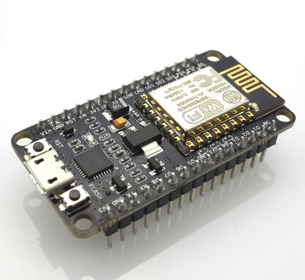
This ESP8266 development board really looks like an Arduino Nano. Speaking of Arduino, another advantage of this board is that you can connect it directly to your PC or Mac and program it like an Arduino! In fact, that's what I'm going to show you in this tutorial.
Video Tutorial
Here's how to program the NodeMCU using the Arduino IDE.
Step 1: Connect your NodeMCU to your computer
You need a USB micro B cable to connect the board. Once you plugged it in, a blue LED will start flashing. If your computer is not able to detect the NodeMCU board, you may need to download the driver on this page.
Step 2: Open Arduino IDE
You need to have at least Arduino IDE version 1.6.4 to proceed with this.
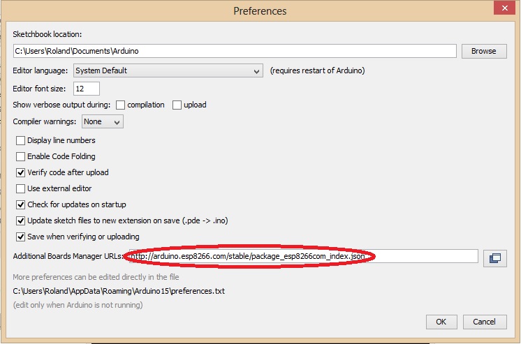
Go to File > Preferences. In the "Additional Boards Manager URLs" field, type (or copy-paste) http://arduino.esp8266.com/stable/package_esp8266com_index.json. Don't forget to click OK!
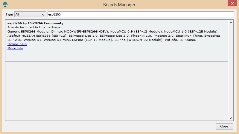
Then go to Tools > Board > Board Manager. Type "esp8266" in the search field. The entry "esp8266 by ESP8266 Community" should appear. Click that entry and look for the install button on the lower right.
Once the download is complete, you can start coding!
Step 3: Make a LED blink using NodeMCU
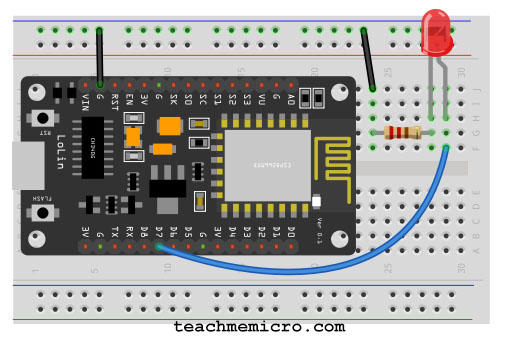
For our first program, we'll blink a LED connected to one of the digital pins of the board. But before that, you need to know that the pin names printed on the board are not the pin names we'll be using for our program. BTW, I'm using NodeMCU V1.0. See my NodeMCU pinout article if you have the other versions of the board.
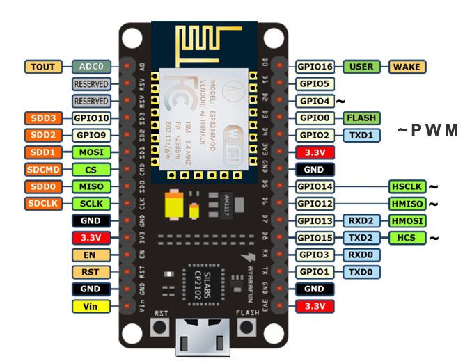
In this example, I'll connect the LED to D7 as it is printed on the board. D7 is GPIO13 according to the image above. You can follow the wiring diagram below:
And so here's my code (which is basically the example Blink code in Arduino):
// the setup function runs once when you press reset or power the board
void setup()
{
// initialize digital pin 13 as an output.
  pinMode(13, OUTPUT);
}

// the loop function runs over and over again forever
void loop()
{
  digitalWrite(13, HIGH);
  // turn the LED on (HIGH is the voltage level)
  delay(1000);
  // wait for a second
  digitalWrite(13, LOW);
  // turn the LED off by making the voltage LOW
  delay(1000); // wait for a second
}
Click the upload button and wait for the "Done Uploading" text to appear.
It's alive!
On my next post, we'll be controlling the LED via a web browser.

