
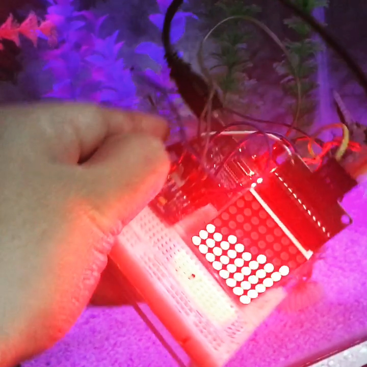
This project makes the “dots” on a dot matrix look like they are pebbles in a container. Tilt the device on one side and the dots fall toward that side. The same goes if the device tilts to the other side.
Materials
- Arduino (Uno/Nano/Micro)
- Single LED Dot Matrix
- MPU6050 Breakout Board
- Breadboard, connecting wires
Theory/Concept
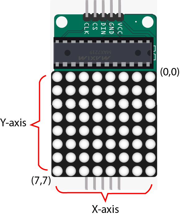
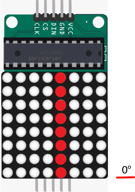
The dots in a single LED matrix follow a coordinate system, with the horizontal the x-axis and the vertical the y-axis. You can set your own origin point by mounting the dot matrix whichever your like; In my case, the origin point is the upper right corner.
The device may only tilt to the left or to the right. This means it’s only tilting on one axis.
I used an MPU6050 accelerometer + gyroscope to detect the movement. Jeff Rowberg’s library provides examples on how to measure the yaw, pitch and roll movements of the device. This is again, depending on how you mount the MPU6050 against the dot matrix. On my setup, I only need to read the roll of the MPU6050.
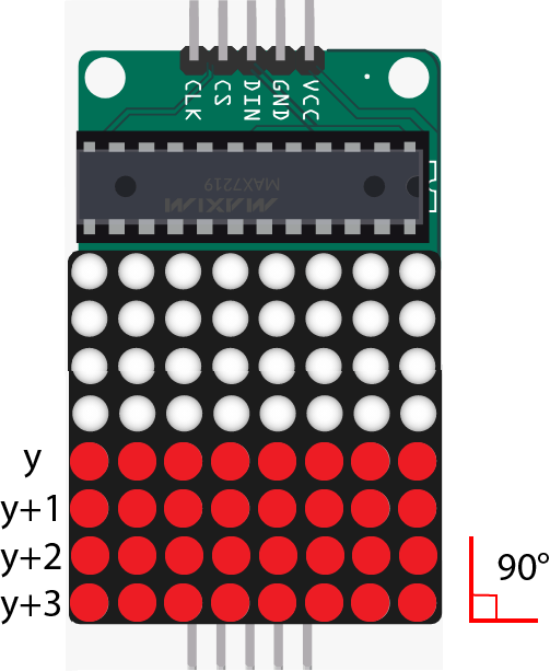
It’s much easier to analyze first if I just select a single row of dots. Then I divided the movements into two steps. First is from the initial position to the 45 inclined position:
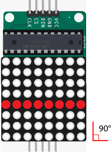
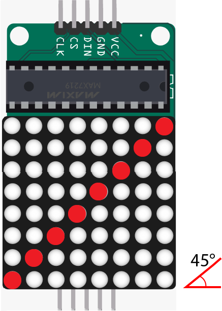
The rightmost dot would have to move four positions to get to its final position on the 2nd image. The second from the right would have to move three positions and so on. The farther the dot from the center, the greater the distance it has to travel to get to its final position.
My algorithm is to set the movements of the dots against their initial position, using Arduino’s map() function:
for(int i=0;i<8;i++){
  int a = u[i][1]+ u[i][0] - 4;
  m[i] = map(angle,90,45,u[i][1],a);
  n[i] = u[i][0];
  for(int j=0;j<8;j++){
    lmd.setPixel(m[i]+j,n[i],true);
  }
}
Here, setPixel() is a function that turns on a dot in a specific coordinate. This function is from LedMatrixDriver library I am using for this project.
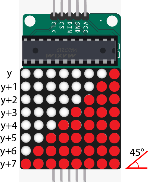
The second step is from the 45 degree inclined position to the upright position:
Here, instead of moving up in the y-axis, the dots need to move right in the x-axis to reach their final destination.
The algorithm now is:
for(int i=0;i<8;i++){
  p[i] = map(angle,45,0,u[i][0],4);
  q[i] = u[i][0];
  for(int j=1;j<8;j++){
    lmd.setPixel(q[i],p[i]-j,true);
  }
}
To fill up the dot matrix, I just increment/decrement the position of the line of dots:
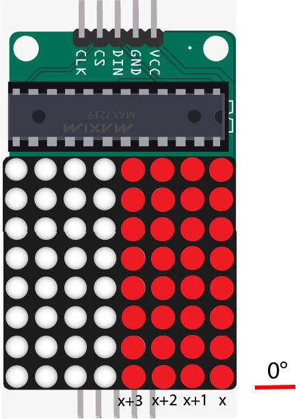
The same concept follows if the device is tilted to the left.
Wiring
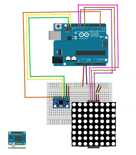
| Arduino UNO | MPU6050 |
|---|---|
| A4 | SDA |
| A5 | SCL |
| D2 | INT |
| 5V | VCC |
| GND | GND |
| Arduino UNO | Dot Matrix (MAX7219) |
|---|---|
| 11 | DIN |
| 9 | CS |
| 13 | CLK |
| 5V | VCC |
| GND | GND |
Sketch/Code
The code uses the MPU6050 library from Jeff Rowberg and the LedMatrixDriver library. You can read my article on MPU6050 for some basic understanding of the accelerometer and gyroscope. I also wrote a tutorial for using the MAX7219 driver with the LED dot matrix.
The full sketch/code is in my repository.
Output Video
I am still looking to improve this project, particularly adding gravity and momentum effects to make the movements more convincing.
If you have any questions, suggestions or reactions about this project, kindly drop a comment below!

