
Most of the time, the data from a sensor in an IoT application needs to be recorded. This data logging is important for later statistical analysis now most popularly known as data analytics. In this tutorial, we will record the data captured from the sensor to a spreadsheet. Let's build a NodeMCU ESP8266 Google Sheets data logger!
We will be using the same circuit we used in the last tutorial. The new things we need for this tutorial are
- Pushingbox account
- Google Drive account
Pushingbox is an API that will help capture data from the NodeMCU to the Google Sheet. It is necessary because Google does not allow direct logging via HTTP ever since its move to HTTPS.
Step 1: Create a Blank Spreadsheet]
[the_ad id="3059"]
Log-in to your Google Drive account. Create a blank spreadsheet and name it.
Step 2: Create a Form
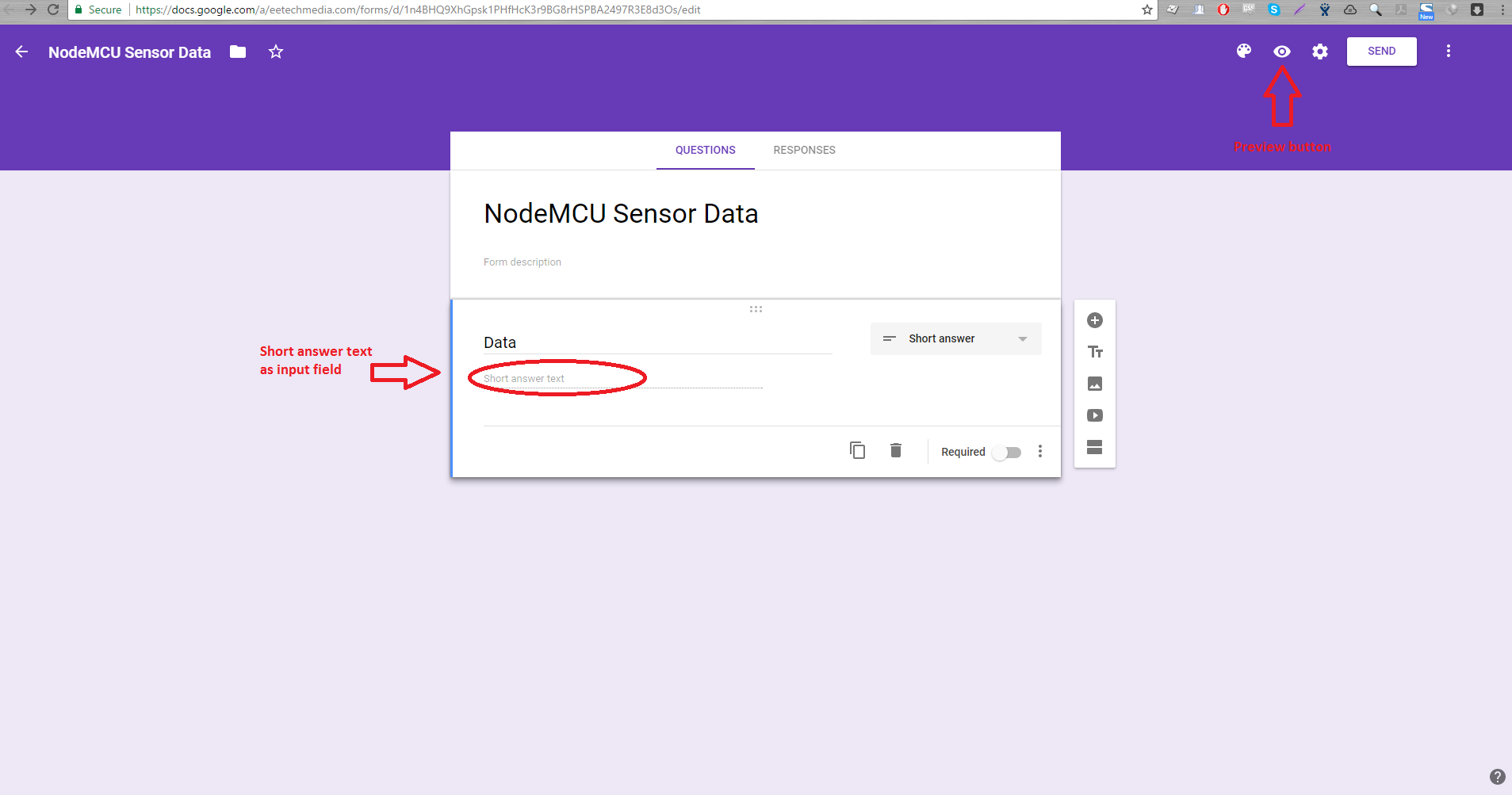
Next, create a new form. Place a "short answer text" as an input field. Then on the upper right corner, click the preview button. This will open a new window.
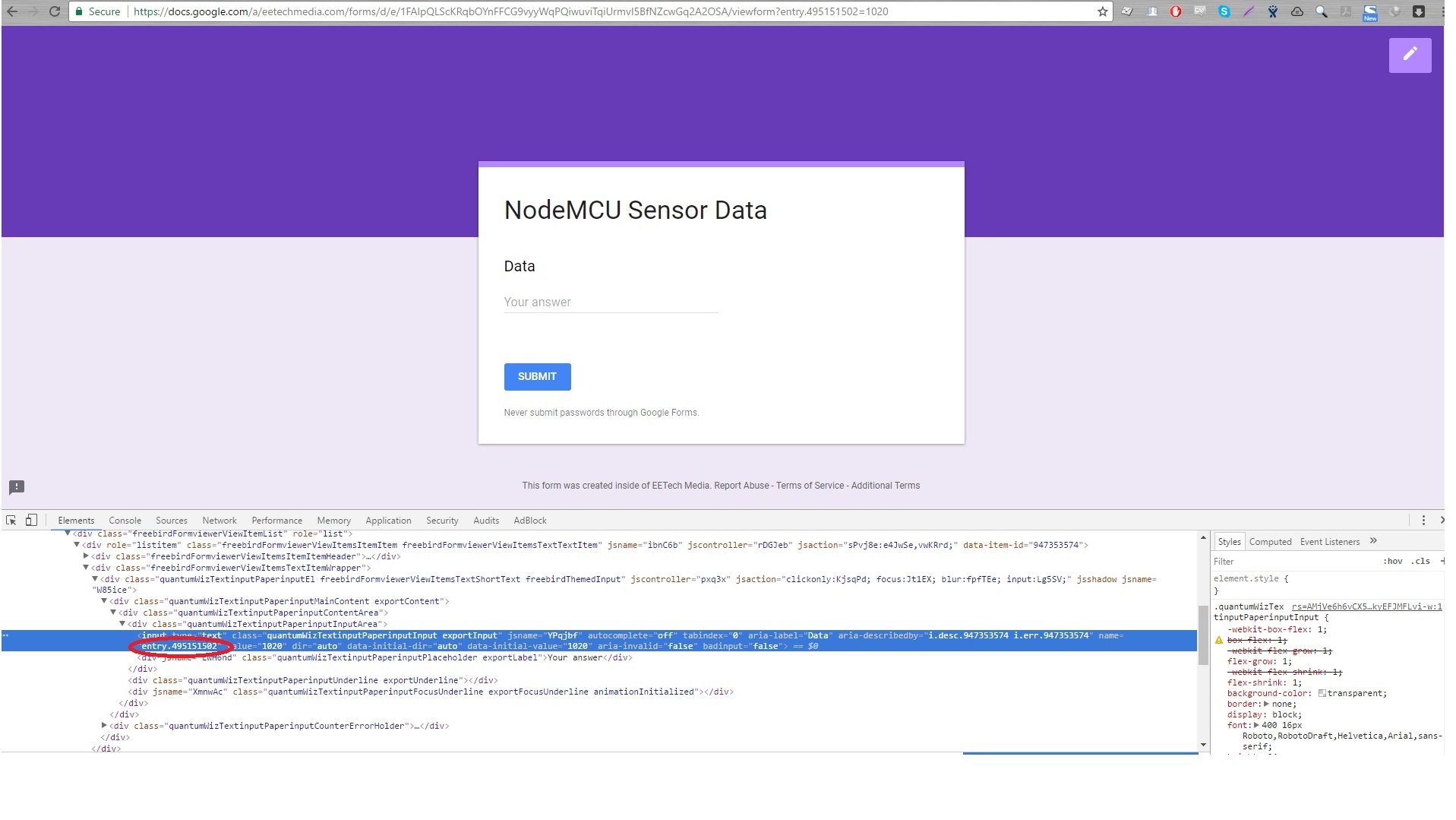
Get the URL of the newly opened window. For example, mine's: the url of this link. Then right-click on the input field you just created and choose "Inspect". On the "Elements" tab, you will acquire the name of the input field. Mine's entry.495151502 as pictured. We need this for later.
[the_ad id="3059"]
Step 3: Link the Form to the Spreadsheet
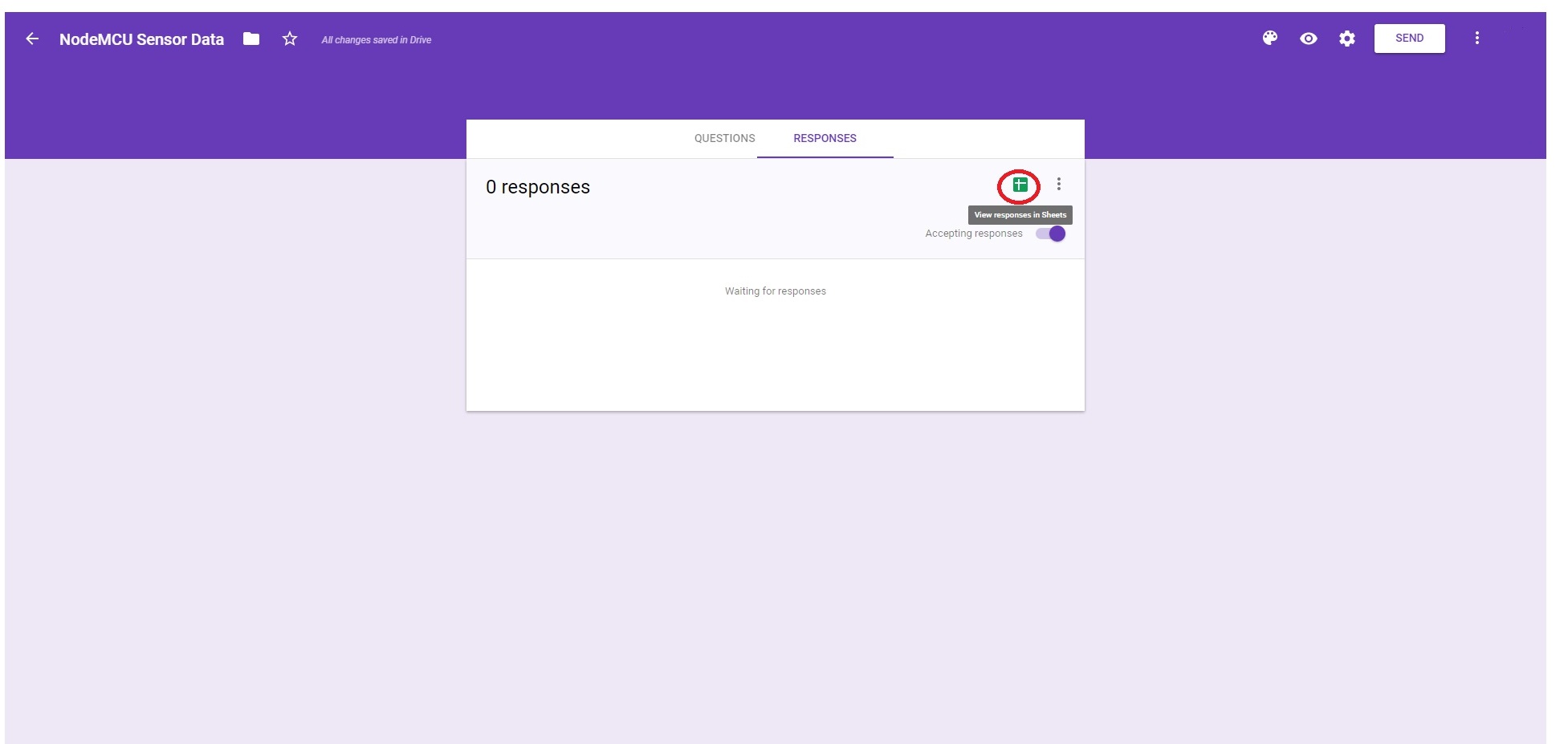
Go back to the previous window (where you edit the form) and click the "Responses" tab. You'll see the Google Sheet icon just above the "Accepting Responses" switch. Click it and a window will pop out. Choose "Select existing spreadsheet" and click "Select". Choose the spreadsheet you created in Step 1.
Step 4: Configure Pushingbox
[the_ad id="3059"]
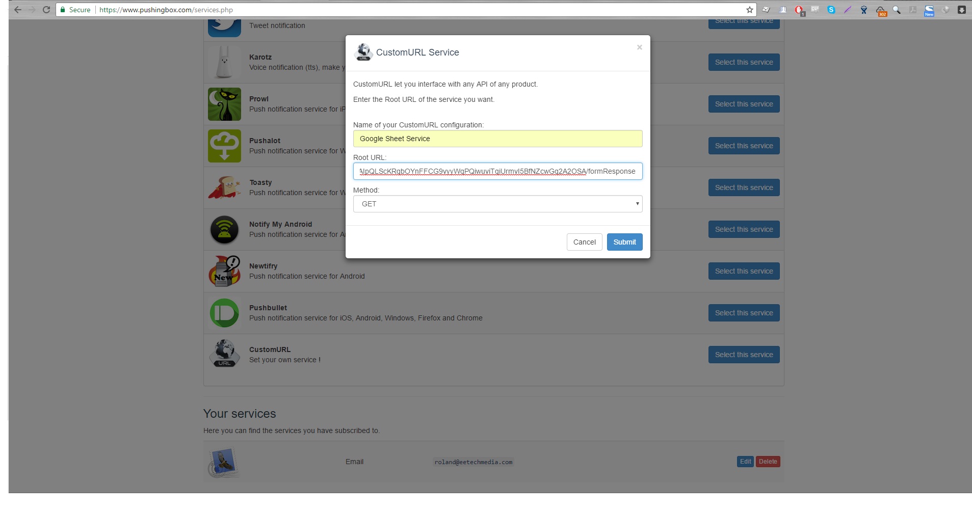
Now go to pushingbox.com and create an account using the same email you used for Google drive. Click the "My Services" tab and click the "Add a service" button. Select "CustomURL". Fill in the form that popped out. Name the service then on the Root URL field, paste the Google Form URL BUT replace "viewform" with "formResponse". Example, using the url above, that would be the url of this link . Leave the Method field as GET.
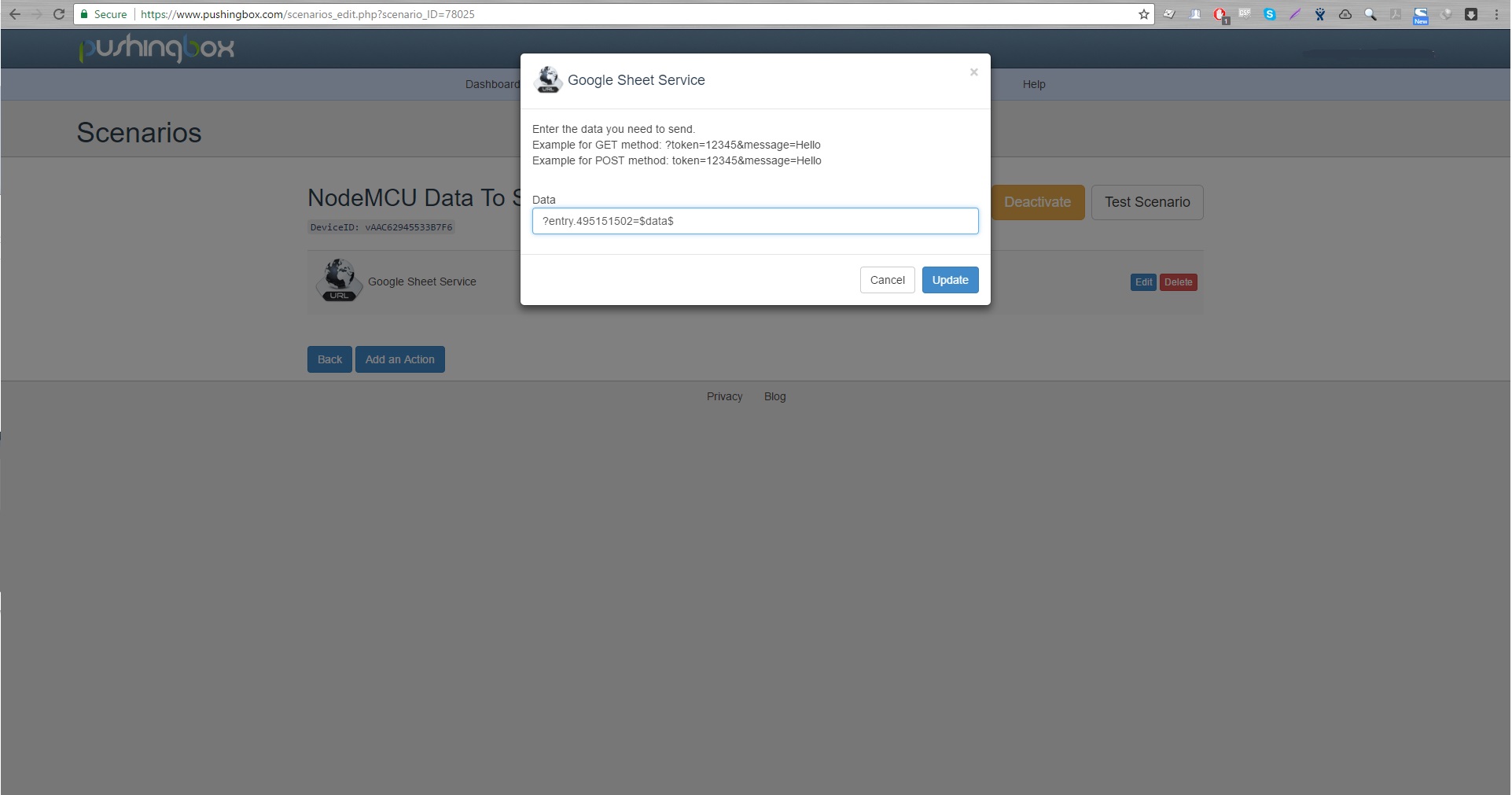
Next, go to "My Scenarios". On the text field, give a name for the scenario and click "Add". Then click "Add an Action". Click the "Add an action with this service" of the service you just created. On the field on the window that pops out, type in the name of the input field in the form plus the "=$data$". You will be given a device ID after that.
Step 5: Write the NodeMCU Code
After getting the device ID, its time to write a code for the NodeMCU. Here's mine:
#include <ESP8266WiFi.h>

const char* ssid     = "<Your SSID>";   //replace with your own SSID
const char* password = "<Your Password>";    //replace with your own password
const char* host = "api.pushingbox.com";

int button = 4;
double data;

void setup() {
  Serial.begin(115200);
  delay(10);

  // We start by connecting to a WiFi network
  Serial.println();
  Serial.println();
  Serial.print("Connecting to ");
  Serial.println(ssid);

  /* Explicitly set the ESP8266 to be a WiFi-client, otherwise, it by default,
     would try to act as both a client and an access-point and could cause
     network-issues with your other WiFi-devices on your WiFi-network. */
  WiFi.mode(WIFI_STA);
  WiFi.begin(ssid, password);

  while (WiFi.status() != WL_CONNECTED) {
    delay(500);
    Serial.print(".");
  }

  Serial.println("");
  Serial.println("WiFi connected");
  Serial.println("IP address: ");
  Serial.println(WiFi.localIP());

  pinMode(A0, INPUT);
  pinMode(button, INPUT);
}

void loop() {
 if(digitalRead(button) == 0){
    delay(1000);
    data = analogRead(A0);
    Serial.print("connecting to ");
    Serial.println(host);

    // Use WiFiClient class to create TCP connections
    WiFiClient client;
    const int httpPort = 80;
    if (!client.connect(host, httpPort)) {
      Serial.println("connection failed");
      return;
    }

    // We now create a URI for the request
    String url = "/pushingbox?";
    url += "devid=";
    url += "<your device ID here>";
    url += "&data="+String(data);

    Serial.print("Requesting URL: ");
    Serial.println(url);

    // This will send the request to the server
    client.print(String("GET ") + url + " HTTP/1.1\r\n" +
               "Host: " + host + "\r\n" +
               "Connection: close\r\n\r\n");
    unsigned long timeout = millis();
    while (client.available() == 0) {
      if (millis() - timeout > 5000) {
      Serial.println(">>> Client Timeout !");
      client.stop();
      return;
    }
  }

  // Read all the lines of the reply from server and print them to Serial
  while(client.available()){
    String line = client.readStringUntil('\r');
    Serial.print(line);
    Serial.print("Data Sent!");
  }

  Serial.println();
  Serial.println("closing connection");
  }
}
Don't forget to replace with your WiFi's SSID and password. Also, provide your device ID on line 58.
[the_ad id="3059"]
The data will be logged to the spreadsheet everytime pin D2 is grounded. If you decide to remove this control then the code will continuously send data to the spreadsheet. Note that pushingbox allows only 1000 requests per day.
If you have any questions regarding this tutorial, kindly drop a comment below and I'll respond right away. Try it now!

