
The emergence of the ESP8266 WiFi module has allowed makers and enthusiasts to create Internet-enabled projects at a minimal cost. Moreover, the popularity of the module also gave rise to commercial boards like the NodeMCU, WeMos D1, Adafruit’s Huzzah. Sparkfun’s ESP8266 Thing and many others. Practicality would make you just buy one of these boards and add it to your project. But wouldn’t it be awesome if you can build your own ESP8266 board?
This is the first part of a series where I document how I created my own ESP8266 board, starting with building the schematic and PCB, testing and creating basic libraries for the XC8 compiler.
This article is sponsored by JLCPCB
The ESP8266 Module
ESP8266 is made by Espressif Systems, a company based on Shanghai, China. The ESP8266 chip, at its earliest days, was very hard to use primarily because of the lack of English documentation. It was not until a number of users expressed interest to the chip that translations of the documentation arose. As of this writing, there are 20 ESP boards each with their own characteristics.
For this project, I will be exclusively using the ESP-12F module:
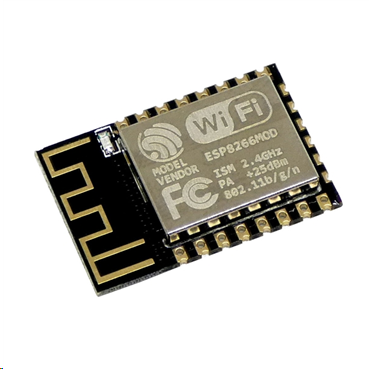
There’s two reasons why I chose this module: the built-in antenna and the ready-to-solder pinouts.
Here is the pinout of the ESP-12F module courtesy from cholla.mmto.org
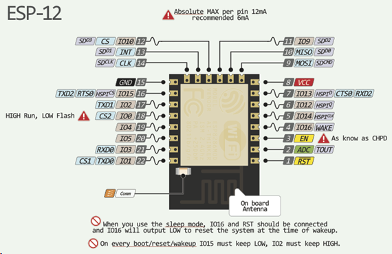
The ESP8266 is a microcontroller by itself. In fact, you could use the Arduino IDE to program it, only needing a USB-to-Serial module if using the ESP-12F as seen above. The board I will be building will not feature the ESP8266 alone. I believe we already have the NodeMCU, WeMos D1, etc. for that. Instead, I will try to build a board so that the PIC16F877A will have an Internet connection via the ESP8266.
Getting the Module Ready
There are some things I needed to take note before designing my schematic:
- The ESP module runs on 3.3 V. All of its pins are not tolerant of voltages up to 3.6 V.
- Each pin can source out and sink in 12 mA
- I need to enable the chip by connecting the EN (CHPD) pin to VCC via a 10k resistor
- IO15 must be grounded with 10k resistor to disable SD card boot mode
- IO0 must have a button for programming mode, pulled up to VCC via 10k resistor and pulled down to ground via 470 ohm resistor.
- The reset pin (RST) needs a button and must be pulled up to VCC via 10k resistor
- IO2 must not be connected to anything
The PIC16F877A will not turn-on when powered less than 4 V so direct connection to the ESP module is impossible. Therefore, I need a level shifter to convert 5 V to 3.3 V. This is aside from the LM1117 regulator that I’ll be using for the ESP’s power supply. For the level converter, I decided to use 74LCX245 IC.
Schematic Diagram
With those things above in mind, I was able to create the schematic for my own ESP8266 board:
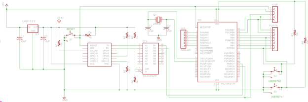
So basically, the ESP8266 will only act as a serial to WiFi bridge for the PIC16F877A. I’ve also added some headers for digital and analog input and for ICSP. Power will be coming from the ICSP and there is no USB to TTL chip. I’ll look into adding a USB to TTL chip for the next version.
PCB Layout
Then, I created the PCB layout using Eagle:
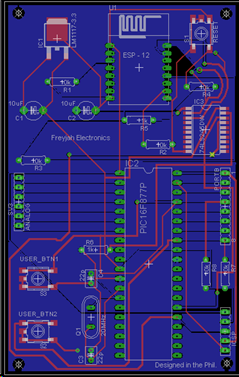
What’s left is to have JLCPCB build the PCB for this prototype. Once it’s delivered, I’ll create another post for testing this PIC16F877A ESP8266 board. I hope you come back!"

