
Global Positioning System (GPS) has been around since the 80's and is still one of the most important features you can add to any electronic system. The idea of tracking something (or someone) is cool enough but doing so without a telephone or an internet connection is much cooler. In this Arduino GPS tutorial, we will discuss the basics of GPS and hopefully guide you in building Arduino GPS projects.
GPS Basics
There's a lot to know about GPS and only a few details on it will be included here. The official website has lots of information and of course, Wikipedia has you covered.
How Location is Tracked
The whole GPS system depends on 24 (minimum) satellites orbiting the earth. Each satellite continually broadcasts their current time and position. Generally, a GPS receiver requires a connection to at least four of these satellites to acquire data to compute for position. The receiver also computes the clock difference between it and the satellite.
The standard horizontal accuracy of a GPS receiver is 15 meters. Augmentation schemes like WAAS and DGPS are implemented to improve accuracy to within 2-3 meters. Assisted GPS (A-GPS) is another augmentation scheme mostly utilized by mobile phones. In this scheme, the GPS receiver seeks "assistance" from mobile networks to improve accuracy.
NMEA Sentences
The computed longitude, latitude, and altitude can be read by devices using the NMEA 0183 protocol. This protocol creates "sentences" in ASCII format that contain those data plus additional information like bearing and speed. Each sentence starts with a set of $GPXXX codes that describes what information is contained within the sentence. Here's a list of all those codes.
Out of all those codes, only 19 have been interpreted. Out of all those 19, only one code type is generally used to read location: $GPRMC which is defined as "Recommended minimum specific GPS/Transit data".
Here's an example $GPRMC sentence:
$GPRMC,220516,A,5133.82,N,00042.24,W,173.8,231.8,130694,004.2,W*70
The sentence above contains 9 information:
- 220516 - time in UTC. This would be 10:05:16 PM
- A - validity. A=valid, V=invalid
- 5133.82, N - latitude
- 0.0042.24, W - longitude
- 173.8 - speed of receiver in nautical miles per hour (knots)
- 231.8 - true course in degrees
- 130694 - date in UTC. This would be June 13, 1994
- 004.2, W - magnetic variation in degrees
- *70 - mandatory checksum
An alternate to $GPRMC is $GPGGA which is defined as "Global Positioning System Fix Data". Here's an example $GPGGA sentence:
$GPGGA,154655,4328.1874,N,00340.5185,W,1,03,08.5,-00044.7,M,051.6,M,,*79
This is what is contained on the sentence above:
- 154655 - time in UTC. This would be 3:46:55 PM
- 4328.1874,N - latitude
- 00340.5185,W - longitude
- 1 - GPS quality indicator. 0 is invalid, 1 is GPS fix, 2 is differential GPS fix
- 03 - number of satellites in use
- 08.5 - horizontal dilution of position
- -00044.7,M - antenna altitude above/below mean sea level, in Meters
- 051.6,M - geoidal separation, in Meters
- (blank) - age in seconds since last update from diff. reference station (blank because GPS quality indicator is GPS fix)
- (blank) - difference reference station ID (also blank because of GPS fix mode)
- *79 - mandatory checksum
Because NMEA sentences are strings, we can simpy extract the information we need through various programming techniques.
Interfacing with GPS Devices
The NMEA sentences can be read from GPS devices via serial communication, particularly RS-232. Therefore any microcontroller with USART features can read data from a GPS peripheral.
Arduino GPS
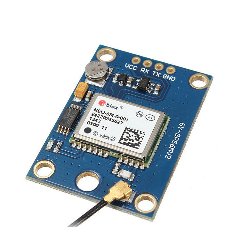
To follow this tutorial, you can use any GPS module that supports NMEA and UBlox protocol via serial communication similar to this GPS module. I used the NEO-6M GPS module in this tutorial.
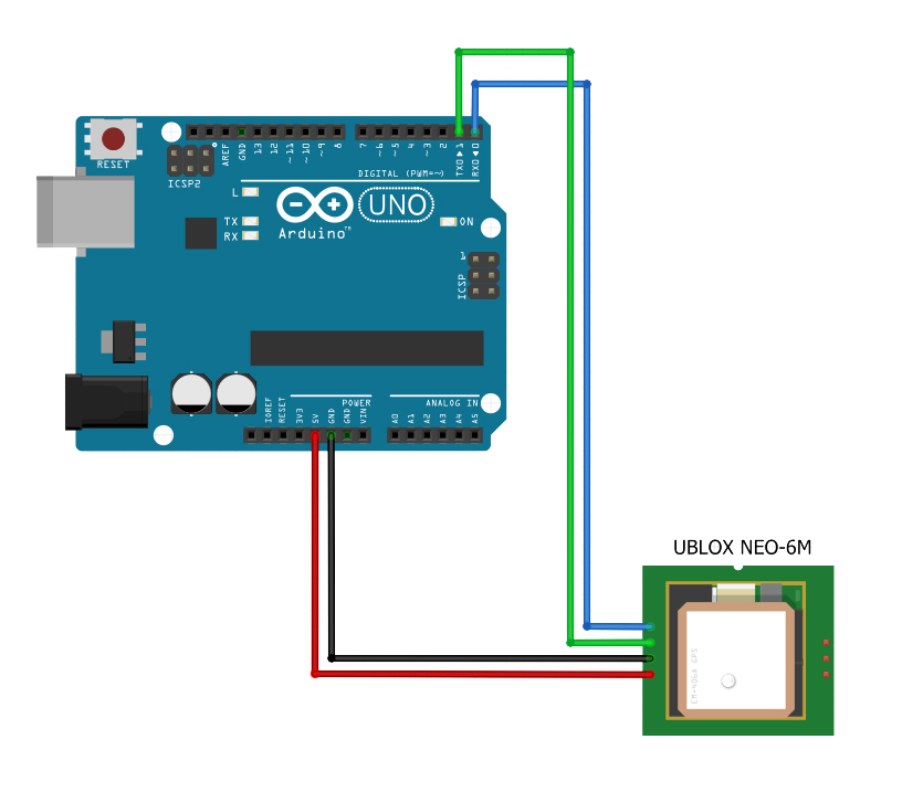
You can use an Arduino as a serial-to-usb converter just to check if your GPS receiver is working. This tutorial features the NEO-6M GPS module.
Connect the GPS as follows:
Open your serial monitor. If you are in an open area, you should see something like this:
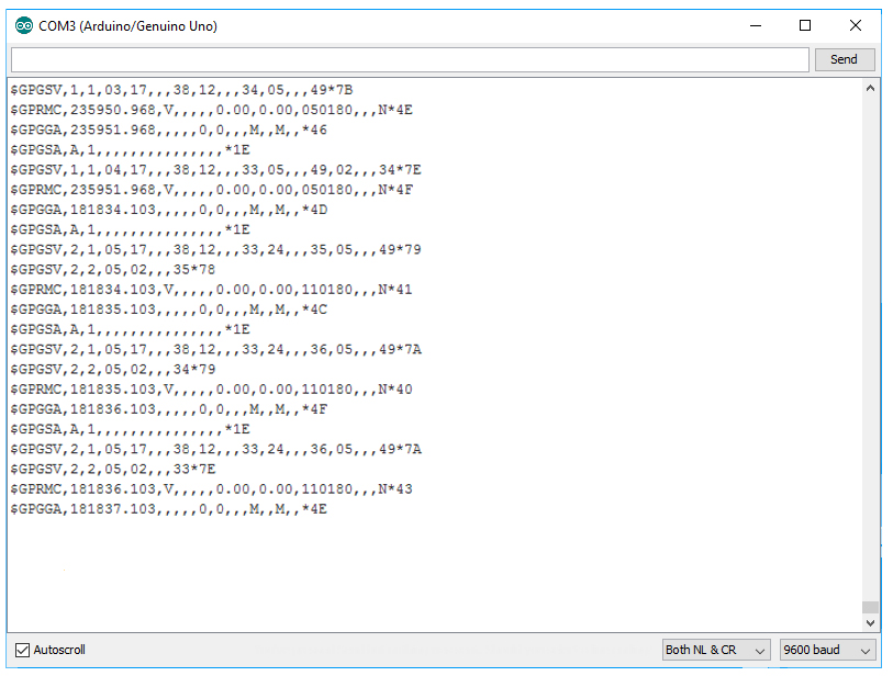
If you are inside a room, your GPS might not receive information from satellites and would display like this:
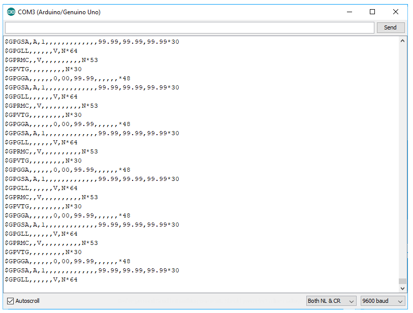
For best results, see to it that the GPS antenna can "see" the sky.
If you are building a project, it would be better if you free up the hardware serial port for debugging and connect the GPS device to other pins. Here is an example diagram:
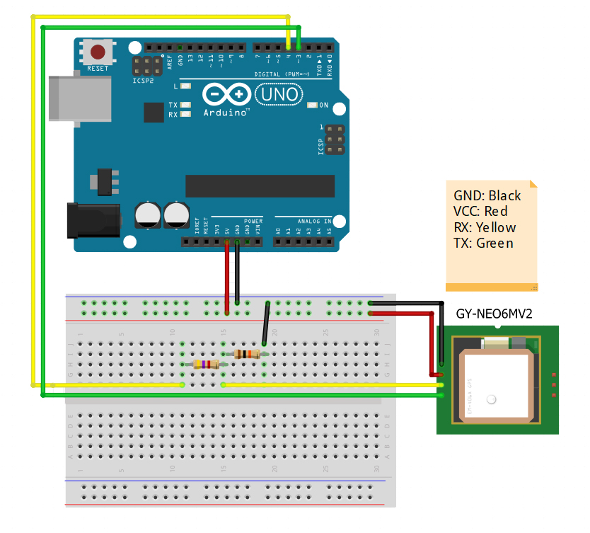
This one uses Software Serial mapped to pins 3 and 4. The GY-NEO6MV2 GPS receiver uses 3.3V logic levels hence a voltage divider is needed to step down the voltage from the Arduino.
You can use the TinyGPS++ library for easier Arduino GPS interfacing. Here's an example sketch from the library (modified to fit diagram above):
#include <TinyGPS++.h>
#include <SoftwareSerial.h>

static const int RXPin = 4, TXPin = 3;
static const uint32_t GPSBaud = 9600;

// The TinyGPS++ object
TinyGPSPlus gps;

// The serial connection to the GPS device
SoftwareSerial ss(RXPin, TXPin);

void setup()
{
  Serial.begin(115200);
  ss.begin(GPSBaud);

  Serial.println(F("DeviceExample.ino"));
  Serial.println(F("A simple demonstration of TinyGPS++ with an attached GPS module"));
  Serial.print(F("Testing TinyGPS++ library v. ")); Serial.println(TinyGPSPlus::libraryVersion());
  Serial.println(F("by Mikal Hart"));
  Serial.println();
}

void loop()
{
  // This sketch displays information every time a new sentence is correctly encoded.
  while (ss.available() > 0)
    if (gps.encode(ss.read()))
      displayInfo();

  if (millis() > 5000 && gps.charsProcessed() < 10)
  {
    Serial.println(F("No GPS detected: check wiring."));
    while(true);
  }
}

void displayInfo()
{
  Serial.print(F("Location: "));
  if (gps.location.isValid())
  {
    Serial.print(gps.location.lat(), 6);
    Serial.print(F(","));
    Serial.print(gps.location.lng(), 6);
  }
  else
  {
    Serial.print(F("INVALID"));
  }

  Serial.print(F("  Date/Time: "));
  if (gps.date.isValid())
  {
    Serial.print(gps.date.month());
    Serial.print(F("/"));
    Serial.print(gps.date.day());
    Serial.print(F("/"));
    Serial.print(gps.date.year());
  }
  else
  {
    Serial.print(F("INVALID"));
  }

  Serial.print(F(" "));
  if (gps.time.isValid())
  {
    if (gps.time.hour() < 10) Serial.print(F("0"));
    Serial.print(gps.time.hour());
    Serial.print(F(":"));
    if (gps.time.minute() < 10) Serial.print(F("0"));
    Serial.print(gps.time.minute());
    Serial.print(F(":"));
    if (gps.time.second() < 10) Serial.print(F("0"));
    Serial.print(gps.time.second());
    Serial.print(F("."));
    if (gps.time.centisecond() < 10) Serial.print(F("0"));
    Serial.print(gps.time.centisecond());
  }
  else
  {
    Serial.print(F("INVALID"));
  }

  Serial.println();
}
Upload the sketch to your Arduino. Open your serial monitor and set the baud rate to 115200. If everything was done right, you should see something like this:
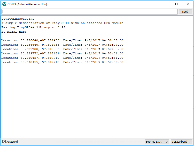
Now you are able to know the location of your Arduino!

