
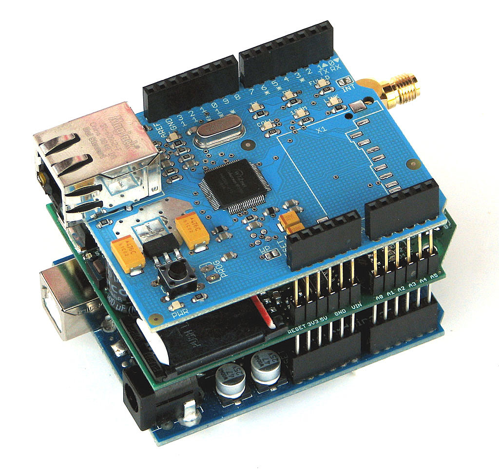
When working on projects, there'll be lots of times when your microcontroller needs serial communication to talk to other devices or other micros. The most common example of this is adding IoT capabilities to your Arduino board or PIC using ESP8266 or GSM module. A number of sensors and LCD displays also send and receive data serially.
What is Serial Communication?
Serial communication is the process of transmitting data one bit at a time. In contrast, parallel communication is where data bits are sent as a whole. Parallel data transmission is faster than serial transmission but with a number of disadvantages:
- It needs more wires and therefore can be more expensive to implement
- The greater number of wires limit it to shorter transmission distances
- It is susceptible to clock skew, which limits the speed of transmission to the slowest of the links
- Crosstalk is also an issue due to the proximity of the wires
Serial data transmission answers all the above problems, most especially the first one, as cost and limited pins are common issues in microcontroller system design.
There are generally two types of serial transmission: asynchronous and synchronous which literally means "not synced" and "synced" respectively. In asynchronous data transfer, there is no clock signal for transmission and reception. The common UART (also known as RS-232 or SCI) device found in microcontrollers is asynchronous. When the communication is synchronous, there is an extra line for the clock signal. I2C and SPI are both synchronous protocols.
The clock signal ensures that reception of correct data bits. In SCI, adding overhead mitigates the effect of the absence of a clock signal. The added overhead affects throughput (the rate of production) since they don't carry useful information. However, the absence of the clock signal also means that SCI is simpler to setup and implement as compared to the complex hardware needed by synchronous protocols.
For the rest of this post, serial will now refer to asynchronous data transmission used by UART devices found in Arduino and PIC microcontrollers. Synchronous data transmission protocols are discussed in their respective articles: SPI, I2C.
The Serial Protocol
Serial communication follows a simple protocol (rules to follow) to ensure correct transmission. A serial data consists of
- Data Bits
- Synchronization Bits
- Parity Bits
The added overhead I was referring to are the synchronization (or sync) and parity bits. The sync bits are start and stop bits to indicate the start and end of transmission. When the serial bus (or data line) is idle, the voltage level goes high. The sending device sends a logic 0 (the start bit) to kickstart the transmission.
Data bits ranging from 5 to 9 bits then follows. The order of data bits is from the least significant bit (LSB) to the most significant bit (MSB).
The transmission of the parity bit, used for error checking, follows. Parity can either be even or odd. For even parity, the parity bit makes the number of 1's even. For odd parity, the parity bit makes the number of 1's odd.
Example: The data bits 1010001 have three 1's. For even parity, the parity bit should be 1 to make the total number of 1's equal to 4 (an even number). For odd parity, the parity bit is 0 since there is already an odd number of 1's.
Stop bits, which is one or two logic 1's, tail the serial data, marking the end of transmission.
The baud rate, or speed of transmission, is also part of the protocol. It is important that the sender and the receiver should have the same baud rate. The standard rates are as follows:
- 1200
- 2400
- 4800
- 9600
- 19200
- 38400
- 57600
- 115200
9600 is the most common and is the default baud rate for most serial terminals and simulators. I'm not sure why is that but I know that 9600 is the maximum serial port speed of old IBM 5150 computers (popularly know as the first "personal computer").
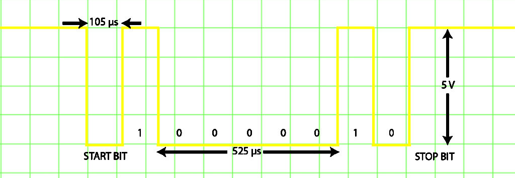
If you connect a serial output pin which sends a "A" (ascii 41 or 01000001 in binary) character to the oscilloscope, this is what you would see on the screen:
Using UART
A microcontrollers UART device has a transmit (Tx) and receive (Rx) line. If you want to interface your micro to another device which uses serial communication, you need to connect the micro's Tx to the device's Rx and vice versa.
The number of UART device varies among microcontrollers. For example, the Arduino UNO's ATMega 328p has one while the Arduino Mega's ATMega 2560 has four.
The PIC16F84A has no UART device. The only way for it to communicate serially is through bit-banging --- a method of directly sending bits by pulling a pin high or low at a specific length of time.
Example: If you want to send the binary data 00110010 serially at a speed of 9,600 baud, you could toggle the state of the Tx pin you assigned based on the binary sequence. The length for which the pin remains on the specified state (1 or 0) would be 104.167 us.
Arduino's software serial library and PBP's SEROUT command uses bit banging.
By experience, software serial is more susceptible to transmission errors than using hardware UART. The only reason I use software serial is when I need to use multiple serial devices at once. I highly recommend using the hardware UART if you are only using one serial device and your microcontroller supports one.
PICs like the PIC16F877A or PIC16F628A each has one UART module. The Beaglebone Black and Raspberry Pi also contain serial communication hardware.
Serial with Arduino
Hardware Serial
Arduino boards communicate with the PC via USB cable or to other serial devices using the serial pins. Each arduino board has at least one serial port and is at digital pins 0 and 1 (Tx and Rx respectively). Using these pins while loading a program to the board causes an error because it's the same pins for USB connection.
The arduino serial port uses TTL signal levels, which means the logic 1 is +5V and logic 0 is 0 V. A computer's serial port uses different voltage levels: the logic 1 is -3 to -25 V while the logic 0 is +3 to +25 V. This is why it's a bad idea to connect the arduino's serial pins directly to a PC's serial port.
The USB port (which is also serial) also uses different voltage levels and protocol. Arduino boards have USB to TTL chips included to interface the board to the computer via USB. Some ATMega micros have bootloaders that doesn't require a USB to TTL chip.
The AnalogReadSerial example is one of the best starting points in understanding how to use the arduino's serial port. Open it using the arduino IDE: File -> Examples -> Basics -> AnalogReadSerial
void setup() {
  // initialize serial communication at 9600 bits per second:
  Serial.begin(9600);
}

// the loop routine runs over and over again forever:
void loop() {
  // read the input on analog pin 0:
  int sensorValue = analogRead(A0);
  // print out the value you read:
  Serial.println(sensorValue);
  delay(1);        // delay in between reads for stability
}
The Serial.begin() function specifies the baud rate. Here it is set to 9600 baud.
This example reads analog voltage at pin A0 and stores it to the variable sensorValue. The sensorValue is now visible in the serial terminal via the Serial.println() function.
If you want your arduino to receive data, you'll be using the Serial.read() function like how it's use below:
String inputString = "";         // a string to hold incoming data
boolean stringComplete = false;  // whether the string is complete

void setup() {
  // initialize serial:
  Serial.begin(9600);
  // reserve 200 bytes for the inputString:
  inputString.reserve(200);
}

void loop() {
  serialEvent(); //call the function
  // print the string when a newline arrives:
  if (stringComplete) {
    Serial.println(inputString);
    // clear the string:
    inputString = "";
    stringComplete = false;
  }
}

/*
  SerialEvent occurs whenever a new data comes in the
 hardware serial RX.  This routine is run between each
 time loop() runs, so using delay inside loop can delay
 response.  Multiple bytes of data may be available.
 */
void serialEvent() {
  while (Serial.available()) {
    // get the new byte:
    char inChar = (char)Serial.read();
    // add it to the inputString:
    inputString += inChar;
    // if the incoming character is a newline, set a flag
    // so the main loop can do something about it:
    if (inChar == '\n') {
      stringComplete = true;
    }
  }
}
For more information on arduino's serial functions, check out the official documentation Arduino Serial.
Arduino Software Serial
Running out of pins to use is common in microcontroller programming. This is especially true for the Arduino UNO which has only one serial port. The GSM module in fact uses software serial to communicate witht the arduino board. Arduino's software serial library is demonstrated by the included built-in example File -> Examples -> Software Serial -> SoftwareSerialExample:
#include <SoftwareSerial.h>

SoftwareSerial mySerial(10, 11); // RX, TX

void setup()
{
  // Open serial communications and wait for port to open:
  Serial.begin(57600);
  while (!Serial) {
    ; // wait for serial port to connect. Needed for Leonardo only
  }

  Serial.println("Goodnight moon!");

  // set the data rate for the SoftwareSerial port
  mySerial.begin(4800);
  mySerial.println("Hello, world?");
}

void loop() // run over and over
{
  if (mySerial.available())
    Serial.write(mySerial.read());
  if (Serial.available())
    mySerial.write(Serial.read());
}
You can assign whichever pins are available for use as Tx and Rx pins! (The above code assigns the serial pins to digital pins 10 and 11). Once there is s software serial object, you can now use the functions of the library which are the basically the same functions as with hardware serial.
Serial with PICs
Software Serial
As mentioned, the PIC16F84A has no serial port. The only way to implement it is through software. In PBP, software serial is done by the SEROUT command. The syntax of the SEROUT command is as follows:
SEROUT Pin, Mode, [Item{,Item...}]
Pin is the name of the Tx pin (e.g. PORTB.0) and Mode is based on this table:
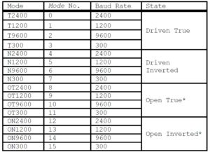
Item would be the data you would send.
PBP allows string to be sent so SEROUT PORTB.0, 2, ["Hello"] sends Hello to the serial terminal. A numeric item will send the ascii representation of that number. For example, SEROUT PORTB.0,2,[65] will print the character "A" in the serial terminal because 65 is the ascii decimal number for that character. If you want to print the number 65, you need to place a pound sign before the number: SEROUT PORTB.0,2,[#65].
For more info about the SEROUT command, read "Serial with PBP" or the official PBP compiler manual.
Software serial in assembly is longer work. Here's how to send a single character "A" using a single pin as transmitter:
;Software Serial in MPASM
;Sends "A" (Hex 41)
;By OP from teachmemicro.com

list      p=16F84A
#include <p16F84a.inc>


cblock 0x0c
	COUNT1
	COUNT2
	COUNT3
endc

org 0x00
goto start


start	bsf STATUS,5
	movlw 0x00
	movwf TRISB
	bcf STATUS,5
	movlw .30
	movwf COUNT1 ;COUNT1 = 30
	clrf PORTB
init	bsf PORTB,0  ;initialize the TX pin to high

main	call delay2  ;long string o 1's
	bcf PORTB,0  ;start bit!
	call delay
	bsf PORTB,0	 ;LSB = 1
	call delay
	bcf PORTB,0  ;0
	call delay
	call delay   ;0
	call delay   ;0
	call delay   ;0
	call delay   ;0
	call delay
	bsf PORTB,0  ;1
	call delay
	bcf PORTB,0  ;MSB = 0
	call delay
	bsf PORTB,0	 ;stop bit!
	goto init

;a delay of about 105us
delay
loop1	decfsz COUNT1,1
	goto loop1
	movlw .30
	movwf COUNT1
	return

;longer delay subroutine for the long string of 1's (idle)
delay2
loop21	decfsz COUNT2,1
	goto loop21
	decfsz COUNT3,1
	goto loop21
	return

end
Here I created a delay routine to keep the state of the pin for about 105 us (approx. 1/9600). I also needed to keep the line idle for a longer time so that the receiving device can distinguish the start bit and the consequently the rest of the data bits. And so I created another delay (delay2) which lasts for around 65 ms.
The character "A" is 41 in hexadecimal. The LSB is sent first and then the rest of the bits follow. The waveform of the serial data (as seen from an oscilloscope) would look like the image above.
If you want to send a string, then you need to know the binary equivalent of each character in the string and just sent each one after the other like what I did here. But if you want to save time and effort then you probably need to use...
PIC Hardware Serial Using PBP
PBP has the HSEROUT command for sending serial data using the PICs UART device. Naturally, this function is unusable for devices that don't have UART module such as the PIC16F84A. The syntax for this command is simple:
HSEROUT [Item{,Item...}]
Where Item is the data to be sent. Before you can use this command, you need three DEFINES:
DEFINE HSER_RCSTA 90h
DEFINE HSER_TXSTA 20h
DEFINE HSER_BAUD 2400
RCSTA is short for Receive Status and Control while TXSTA is short for Transmit Status and Control. These two are the primary registers you need to manipulate in order to use the hardware UART. The individual bits of these two registers are shown below:
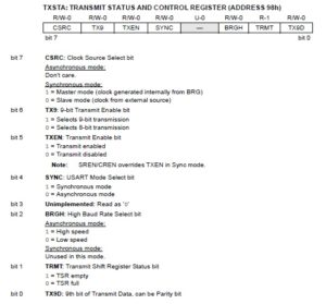
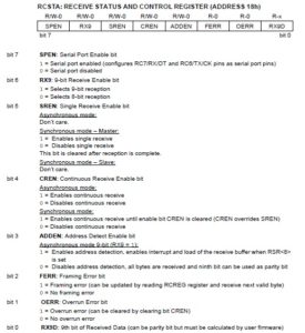
When we did "DEFINE HSER_TXSTA 20h", we set the TXSTA register equal to 20h which is 00100000 in binary. This corresponds to bit 5 (TXEN) being set while the rest of the bits are cleared. This is needed to enable serial transmission from the PIC to another serial device.
Doing "DEFINE HSER_RCSTA 90h" gives the RCSTA register a value of 90h or 10010000 in binary. This sets bit 7 (SPEN) and bit 4 (CREN). The SPEN bit is the master switch of the entire UART module while CREN allows for continuous receiving of bits on the RX pin.
Lastly, "DEFINE HSER_BAUD 2400" sets the baud rate to 2400.
As usual, doing serial using assembly takes time even if we'll now be using the hardware UART. I'll go straight to the example code (I used PIC16F628A btw):
list p = 16F628A
INCLUDE <P16F628A.INC>

	cblock 0x20
		char0
		COUNT1
		COUNT2
	endc

ORG 0x00
goto init

init	clrf PORTB
	clrf PORTA
	bsf STATUS, RP0   ;bank 1
	clrf TRISB        ;all PORTB pins are output
	movlw 01h
	movwf TRISA       ;make all PORTA pins output except RA0
	movlw 07h
	movwf CMCON       ;disable comparator modules
;---CONFIGURE SPBRG FOR DESIRED BAUD RATE
	movlw D'25'       ;baud rate =  9600bps
	movwf SPBRG       ;at 4MHZ
;---CONFIGURE TXSTA
	movlw B'00100100'
	movwf TXSTA
;Configures TXSTA as 8 bit transmission, transmit enabled, async mode, high speed baud rate
	bcf STATUS, RP0   ;bank 0
	movlw B'10000000'
	movwf RCSTA       ;enable serial port receive

	movlw 0x21
	movwf char0       ;put ! (ascii code 21) character to char0 register

main	movf char0, W
	movwf TXREG       ;place the ! character to TXREG
	goto wthere
	goto main

wthere	btfss TXSTA, TRMT ;check if TRMT is empty
    	goto WTHERE       ;if not, check again
	bcf STATUS, RP0   ;bank 0, if TRMT is empty then the character has been sent
	return

	end
Baud Rate Calculations
The baud rate is set by manipulating the SPBRG register and the BRGH bit on TXSTA. The baud rate formulas are as follows:

You can choose between low speed and high speed baud rate by setting or clearing the BRGH bit. The baud rate number doesn't indicate if its high speed or low speed so 9600 baud is possible for both speeds. However, the datasheet recommends using the high speed setting because the baud rate error is said to be smaller. (Notice that you can also choose between asynchronous and synchronous transmission by setting or clearing the SYNC bit --- bit 4 of TXSTA).
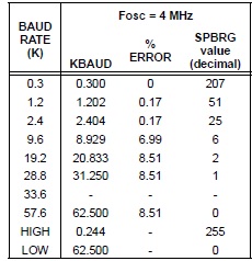
Using the formulas above, the datasheet provided a table for the common baud rates using the usual oscillator values. This is for the 4 MHz oscillator low speed:
This is for the same oscillator at high speed setting:
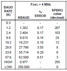
Look at the %ERROR column for the 9,600 baud rate at both tables. That's more than 40x of difference in error!
Now back to the code. I placed the value 25 to the SPBRG register as suggested by the table above. Then I set the TXEN and BRGH bits on the TXSTA register, followed by setting the SPEN bit on the RCSTA register. The next part is placing 21 hex (! character) in the empty register char0.
To send the data, the contents of char0 moves to TXREG register. Checking bit TRMT of the TXSTA register ensures that the data is now out from the buffer and is on its way to the other device.
Again if you need to send a string of characters, you just need to move one character to the TXREG register at a time and wait for the buffer to be cleared by checking if the TRMT bit of the TXSTA register is set every after you sent a character to TXREG.
See Serial Communications with PIC for XC8 UART Coding
Serial with Embedded Linux (Beaglebone Black/Raspberry Pi)
Just like any other peripheral, using serial with the Beaglebone Black and Raspberry Pi involves the use of device tree overlays. I will consider these two as one device since both are inherently Linux computers. If you need a more specific approach, a tutorial on serial for beaglebone black can be found here while a tutorial for raspberry pi serial communication is presented here.
The debug serial ports for both Beaglebone Black and Raspberry Pi are enabled by default. The debug serial port (which is the J1 pins) for the BBB is found in /dev/ttyO0 while the Raspberry Pi serial port is at /dev/ttyAMA0. To use the serial port, you need an app such as minicom. You can install minicom by doing:
sudo apt-get install minicom
Once installed, you can now run the minicom app:
minicom -b 9600 -o -D /dev/ttyO0
or
minicom -b 9600 -o -D /dev/ttyAMA0
After that, anything you'll type on the terminal will be sent out to the serial port. Easy!
The best way to learn more about serial communication with microcontrollers is to code them yourselves! So I suggest you try on the example codes here and then start building projects. I hope you have fun as much as I did!

