
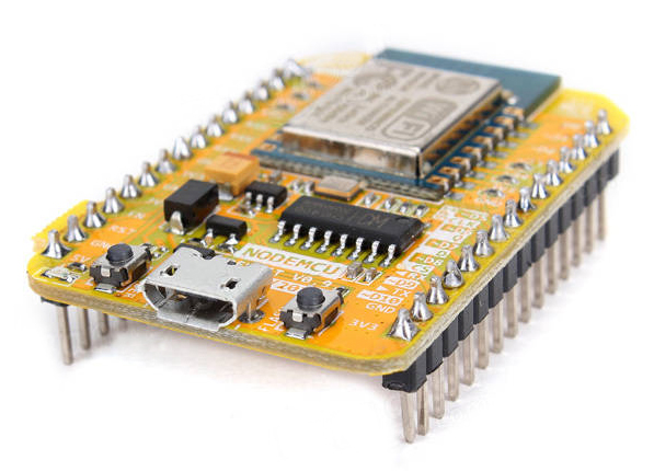
The NodeMCU is an Arduino-compatible board that features the ESP8266 at its core. It became popular because it is a WiFi-ready microcontroller by itself - no need for an Arduino. This NodeMCU pinout reference aims to show pinouts for NodeMCU v0.9, NodeMCU v1.0, and NodeMCU v3.
Note that when programming these boards using the ESP core in Arduino IDE, the GPIO numbers are used instead of what's on the board. For example, if you attach an LED to D7, you will refer to this as 13 on the sketch
NodeMCU V0.9 Pinout
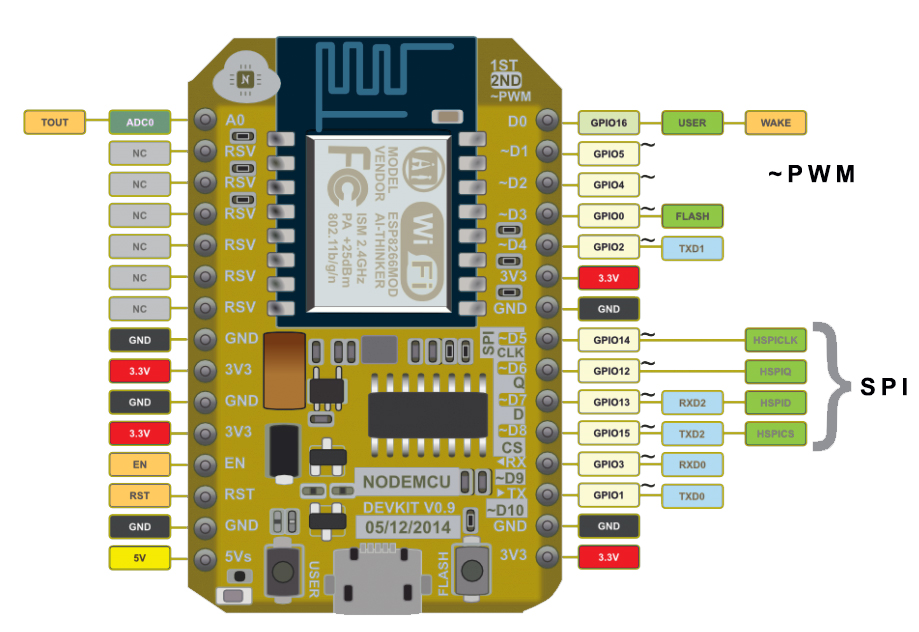
This is the first version of the NodeMCU board featuring the ESP-12. The V0.9 board has since been outdated primarily because of its width which isn't breadboard-friendly. The number of Not Connected (NC) pins is also a reason.
NodeMCU V1.0 Pinout
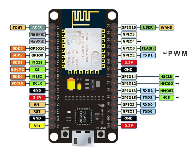
The second generation of the NodeMCU is arguably the most popular one. Amica (the company that created both V0.9 and V1.0) made this board narrower to fit a breadboard. Moreover, the ESP8266 has also been upgraded from ESP-12 to ESP-12E (a few extra pins). This version uses the Silabs CP2102 as the USB controller. You can download the USB driver for this board at this link.
NodeMCU V3 Pinout
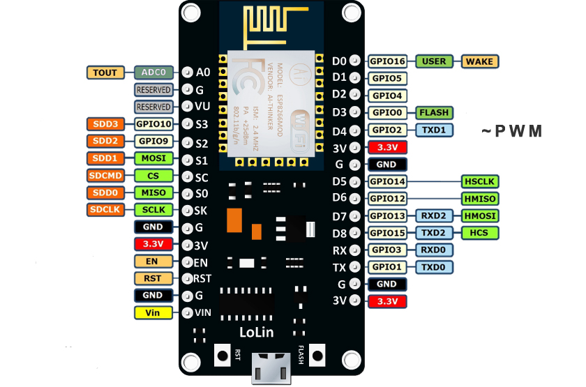
This is a version invented by Lolin with a CH340G USB-TTL chip instead of the Silabs CP2102 from V1.0. As shown, it has the same pinout structure as V1.0. But this board is slightly larger than the V1.0. You can download the CH340G driver at this link.
Important! While it shows 3.3V and the datasheet says so, the 3V pin is indeed 3V only! Connecting a 3.3V device won't work so be aware.
These are the boards that carry the "NodeMCU" name. But they are not the only ones featuring the ESP8266. See Adafruit Huzzah and WeMos D1 Mini.
This NodeMCU Pinout article is for reference only. To know more about how to use this IoT board, see my other tutorials:

