
The MPU6050 is a six-axis gyroscope and accelerometer in one package. With its easy-to-use breakout board, it became one of the more popular sensors for the Arduino platform. This article looks into this sensor and teaches how to use it to determine the orientation of an object.
Introduction
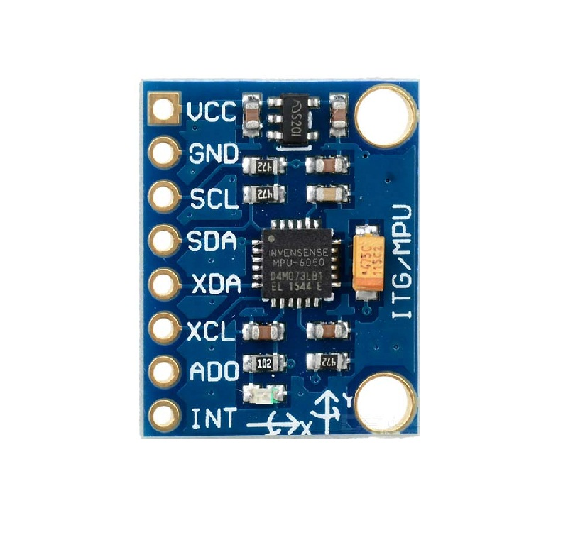
The MPU6050 breakout board comes with 8 pins as shown:

[the_ad id="3059"]
The sensor communicates, as a slave, with a microcontroller through I2C. It can also become an I2C master by connecting another device, most likely a magnetometer, to the XDA and XCL pins. The breakout board also has an 16-bit ADC input pin (AD0). The GY-521 breakout board pictured takes on 5 V as power source.
The breakout board follows the schematic below:

Notable here is that pull-up resistors are already connected to the SDA and SCL pins.
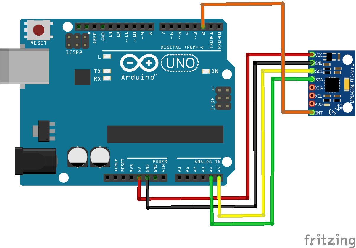
Since the sensor uses I2C and the Arduino has fixed I2C pins, this is the most likely connection you’ll use when using the MPU6050:
More information about the MPU6050 is on its datasheet:
[wpdm_package id='3526']
Next, we’ll write a sketch to print out the orientation of the MPU6050.
Gyroscope vs Accelerometer
Before we proceed to how the MPU6050 can give orientation, let me discuss first what a gyroscope and accelerometer do.
A gyroscope can measure angular velocity, which is the rate of change of the angle an object makes with the x, y and z axes.
Consider the disk below:
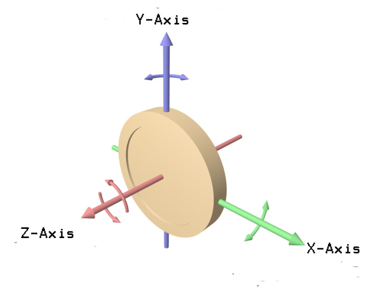
The disk can rotate in six-ways: clockwise and counterclockwise on each of the three axes. If the disk is the MPU6050 then its gyroscope will give an output that describes how fast the disk is rotating on a given axis.
Meanwhile, an accelerometer measures linear acceleration over the same three axes.

Similarly, the disk can move in six ways: back and forth in each of the three axes. If the disk is attached to the MPU6050 then its accelerometer will give an output that describes how fast the disk is moving on a given axis.
Knowing Orientation
Orientation is more formally called Euler angles or yaw (θ) , pitch (ρ) and roll (Φ).

Both pitch and roll can be calculated if the linear acceleration for particular axes are known:
![]()
The yaw angle is trickier because it tends to drift with time and thus needs a constant reference such as a magnetometer or a GPS device. This is exactly the purpose of the XDA and XCL pin: for attaching a magnetometer that can help measure yaw angle.

[the_ad id="3059"]
Another issue is that the formulas above is usable only if the accelerometer values are noiseless. This is hardly the case with most accelerometers.
Thus, determining the Euler angles from raw accelerometer and gyroscope values are not that easy.
The Essential MPU6050 Library
Thankfully, the MPU6050 is different from all other motion sensing devices because of Invensense’s proprietary Digital Motion Processor (DMP).
The DMP takes on both acceleration and gyroscope data and gives out the needed Euler angles and other data.
The DMP is not fully documented until engineers figured it out by reverse engineering Invensense’s MPU6050 dev-kit. The result is the only Arduino MPU6050 library you’ll need: Jeff Rowberg’s library.
Printing Out Orientation
The library comes with several examples for you to get acclimated with it. The MPU6050_DMP6 example will give the acceleration, euler angles and quaternions if you desire. I managed to edit that example to print out just the yaw, pitch and roll values:
#include "I2Cdev.h"
#include "MPU6050_6Axis_MotionApps20.h"

#if I2CDEV_IMPLEMENTATION == I2CDEV_ARDUINO_WIRE
  #include "Wire.h"
#endif

MPU6050 mpu;

// MPU control/status vars
bool dmpReady = false; // set true if DMP init was successful
uint8_t mpuIntStatus; // holds actual interrupt status byte from MPU
uint8_t devStatus; // return status after each device operation (0 = success, !0 = error)
uint16_t packetSize; // expected DMP packet size (default is 42 bytes)
uint16_t fifoCount; // count of all bytes currently in FIFO
uint8_t fifoBuffer[64]; // FIFO storage buffer

// orientation/motion vars
Quaternion q; // [w, x, y, z] quaternion container
VectorFloat gravity; // [x, y, z] gravity vector
float ypr[3]; // [yaw, pitch, roll] yaw/pitch/roll container and gravity vector

volatile bool mpuInterrupt = false; // indicates whether MPU interrupt pin has gone high
void dmpDataReady()
{
  mpuInterrupt = true;
}

void setup()
{
// join I2C bus (I2Cdev library doesn't do this automatically)
#if I2CDEV_IMPLEMENTATION == I2CDEV_ARDUINO_WIRE
  Wire.begin();
  TWBR = 24; // 400kHz I2C clock (200kHz if CPU is 8MHz)
#elif I2CDEV_IMPLEMENTATION == I2CDEV_BUILTIN_FASTWIRE
  Fastwire::setup(400, true);
#endif

mpu.initialize();
Serial.begin(9600);
devStatus = mpu.dmpInitialize();

// supply your own gyro offsets here, scaled for min sensitivity
mpu.setXGyroOffset(220);
mpu.setYGyroOffset(76);
mpu.setZGyroOffset(-85);
mpu.setZAccelOffset(1788); // 1688 factory default for my test chip

// make sure it worked (returns 0 if so)
  if (devStatus == 0)
  {
    // turn on the DMP, now that it's ready
    mpu.setDMPEnabled(true);

    // enable Arduino interrupt detection
    attachInterrupt(0, dmpDataReady, RISING);
    mpuIntStatus = mpu.getIntStatus();

    // set our DMP Ready flag so the main loop() function knows it's okay to use it
    dmpReady = true;

    // get expected DMP packet size for later comparison
    packetSize = mpu.dmpGetFIFOPacketSize();

  }
  else
  {
    // ERROR!
    // 1 = initial memory load failed
    // 2 = DMP configuration updates failed
    // (if it's going to break, usually the code will be 1)
    Serial.print(F("DMP Initialization failed (code "));
    Serial.print(devStatus);
    Serial.println(F(")"));
  }
}


void loop()
{
  // if programming failed, don't try to do anything
  if (!dmpReady) return;

  // wait for MPU interrupt or extra packet(s) available
  while (!mpuInterrupt && fifoCount < packetSize);

  // reset interrupt flag and get INT_STATUS byte
  mpuInterrupt = false;
  mpuIntStatus = mpu.getIntStatus();

  // get current FIFO count
  fifoCount = mpu.getFIFOCount();

  // check for overflow (this should never happen unless our code is too inefficient)
  if ((mpuIntStatus & 0x10) || fifoCount == 1024)
  {
    // reset so we can continue cleanly
    mpu.resetFIFO();
    Serial.println(F("FIFO overflow!"));

  // otherwise, check for DMP data ready interrupt (this should happen frequently)
  }
  else if (mpuIntStatus & 0x02)
  {
    // wait for correct available data length, should be a VERY short wait
    while (fifoCount < packetSize) fifoCount = mpu.getFIFOCount();
    // read a packet from FIFO
    mpu.getFIFOBytes(fifoBuffer, packetSize);
    // track FIFO count here in case there is > 1 packet available
    // (this lets us immediately read more without waiting for an interrupt)
    fifoCount -= packetSize;

    mpu.dmpGetQuaternion(&q, fifoBuffer);
    mpu.dmpGetGravity(&gravity, &q);
    mpu.dmpGetYawPitchRoll(ypr, &q, &gravity);
    Serial.print("Yaw: ");
    Serial.println(ypr[0] * 180/M_PI);
    Serial.print("Pitch: ");
    Serial.println(ypr[1] * 180/M_PI);
    Serial.print("Roll: ");
    Serial.println(ypr[2] * 180/M_PI);
  }
}
[the_ad id="3059"]
Explaining the Sketch
The code might be overwhelming specially to beginners.
Basically the MPU6050 object is initialized:
MPU6050 mpu;
Then a bunch of variable declaration follows:
//MPU control/status vars
bool dmpReady = false; // set true if DMP init was successful
uint8_t mpuIntStatus; // holds actual interrupt status byte from MPU
uint8_t devStatus; // return status after each device operation (0 = success, !0 = error)
uint16_t packetSize; // expected DMP packet size (default is 42 bytes)
uint16_t fifoCount; // count of all bytes currently in FIFO
uint8_t fifoBuffer[64]; // FIFO storage buffer

// orientation/motion vars
Quaternion q; // [w, x, y, z] quaternion container
VectorFloat gravity; // [x, y, z] gravity vector
float ypr[3]; // [yaw, pitch, roll] yaw/pitch/roll container and gravity vector
The MPU6050 sends out an interrupt every time there’s new data available. But the interrupt must only be enabled after the DMP is done. Hence, this part:
volatile bool mpuInterrupt = false; // indicates whether MPU interrupt pin has gone high
void dmpDataReady()
{
 mpuInterrupt = true;
}
Inside setup(), we initialize the MPU6050:
mpu.initialize();
Initialization involves several steps including waking up the device. The DMP also needs to be initialized and the function that does this returns a flag to tell the status:
devStatus = mpu.dmpInitialize();
The offset values, is then provided:
mpu.setXGyroOffset(220);
mpu.setYGyroOffset(76);
mpu.setZGyroOffset(-85);
mpu.setZAccelOffset(1688); // 1688 factory default for my test chip
If the DMP successfully initialized, devStatus will be zero, hence:
if (devStatus == 0)
 {
    // turn on the DMP, now that it's ready
    mpu.setDMPEnabled(true);

    // enable Arduino interrupt detection
    attachInterrupt(0, dmpDataReady, RISING);
    mpuIntStatus = mpu.getIntStatus();

    // set our DMP Ready flag so the main loop() function knows it's okay to use it
    dmpReady = true;

    // get expected DMP packet size for later comparison
    packetSize = mpu.dmpGetFIFOPacketSize();
 }
Here, the DMP is turned on, the interrupt is attached to interrupt 0 (pin 2) and the MPU6050 interrupt status is read. The dmpReady flag is also set to true to signal the loop() function that everything’s good to go. Finally, the expected FIFO packet size is read.
If the devStatus returns a value other than zero, the error handler will trigger:
else{
    // ERROR!
    // 1 = initial memory load failed
    // 2 = DMP configuration updates failed
    // (if it's going to break, usually the code will be 1)
    Serial.print(F("DMP Initialization failed (code "));
    Serial.print(devStatus);
    Serial.println(F(")"));
}
Inside loop(), the sketch waits for an interrupt from the MPU6050 and extra packets from the FIFO:
while (!mpuInterrupt && fifoCount < packetSize);
The sketch never exits this line unless these conditions are met. If the condition are finally met, the interrupt is reset, the interrupt status is acquired and the FIFO data is read:
// reset interrupt flag and get INT_STATUS byte
 mpuInterrupt = false;
 mpuIntStatus = mpu.getIntStatus();

 // get current FIFO count
 fifoCount = mpu.getFIFOCount();
In this case, we only want an interrupt status equal to 0x02 (according to the datasheet). If this is the value of the interrupt status register then it’s now safe to read the data we want.
else if (mpuIntStatus & 0x02)
 {
    // wait for correct available data length, should be a VERY short wait
    while (fifoCount < packetSize) fifoCount = mpu.getFIFOCount();
    // read a packet from FIFO
    mpu.getFIFOBytes(fifoBuffer, packetSize);
    // track FIFO count here in case there is > 1 packet available
    // (this lets us immediately read more without waiting for an interrupt)
    fifoCount -= packetSize;
    mpu.dmpGetQuaternion(&q, fifoBuffer);
    mpu.dmpGetGravity(&gravity, &q);
    mpu.dmpGetYawPitchRoll(ypr, &q, &gravity);

    Serial.print("Yaw: ");
    Serial.println(ypr[0] * 180/M_PI);
    Serial.print("Pitch: ");
    Serial.println(ypr[1] * 180/M_PI);
    Serial.print("Roll: ");
    Serial.println(ypr[2] * 180/M_PI);
 }
Otherwise, we reset the FIFO.
// check for overflow (this should never happen unless our code is too inefficient)

 if ((mpuIntStatus & 0x10) || fifoCount == 1024)
 {
    // reset so we can continue cleanly
    mpu.resetFIFO();
    Serial.println(F("FIFO overflow!"));
 // otherwise, check for DMP data ready interrupt (this should happen frequently)
 }
That’s it! If you encounter any issues with the sketch, feel free to drop a comment below.
[the_ad id="3059"]

