
So far we have discussed how to code microcontrollers sequentially, i.e., the device performs the code from top to bottom and may branch out to labels (via goto) or subroutines (via call). Now we'll be looking at PIC interrupt.
What is a PIC Interrupt?
Interrupts, from the word itself, are events that the microcontroller has to acknowledge even if it is currently executing something.
An analogy of interrupts may be useful. Imagine you reading a book. When your phone rings, you will pause reading, place a bookmark, and then answer the phone. If the number who is calling you is unknown, you would ask for the name of the caller. You will then finish the phone conversation, and return to where you stopped reading.
A similar thing happens with microcontrollers and interrupts: the device is busy with a main process (reading a book) when an interrupt occurs (phone ringing). The device will save the program counter value to the stack (bookmark the page), know which interrupt is triggered (identify the caller) and execute the interrupt routine (talk to the caller). When the interrupt routine is finished, the device will read the program counter from the stack so that it can go back to where it stopped on the main process (pickup the bookmark and go back to reading).
If the interrupts are really important and should not be ignored, we call them non-maskable interrupts. Examples of these are internal memory errors, data corruption and other very important things that would directly affect the operation of the microcontroller. The PIC16F84A has no non-maskable interrupt so all its interrupts can be disabled or enabled via code. I will discuss all of the interrupt types for this microcontroller with example codes in assembly. Codes for CCS C and PBP will also be given in a separate section. Here's a rundown of the interrupts for the PIC16F84A (click to jump to the specified section):
The interrupts are enabled/disable by using the INTCON register (address 0x0B or 0x8B):
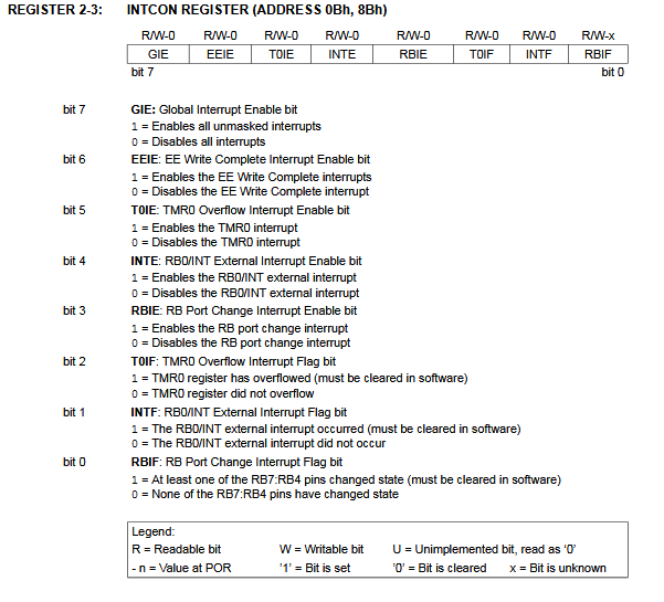
To enable any interrupt, the GIE (bit 7, Global Interrupt Enable) bit should be set. Bit 3 to bit 0 are flag bits which are bits that would set whenever a specific interrupt is triggered.
The advantage of using interrupts over traditional, "linear" microcontroller programming is that you can trigger events almost instantly. For example, if you want to read the state of a button on a pin, you would normally do this:
BTFSS PORTB,0 ;read the state of RB0
GOTO sub1 ;if RB0 is clear, go to sub1
GOTO sub2 ;if RB0 is set, go to sub2
;some code here
In order for the device to detect the pin state change, line 1 must be the current line executed. If the device is already on line 4, pressing the button on RB0 wouldn't trigger anything! However if you use interrupt, it won't matter which line is currently being executed. The interrupt will trigger anytime as long as it is enabled.
External Pin Interrupt
The external pin interrupt is triggered whenever there is a "change of state" on the RB0/INT (pin #6 on the PIC16F84A). The change of state means the pin went from high to low or low to high.
To enable this interrupt, you have to set the INTE (bit 4, External Interrupt Enable) bit of the INTCON register. An example program below illustrates this:
; TODO INSERT CONFIG CODE HERE USING CONFIG BITS GENERATOR
#INCLUDE <PIC16F84A.INC>

RES_VECT  CODE    0x0000            ; processor reset vector
    GOTO    START                   ; go to beginning of program

INT_VECT  CODE	  0x0004	    ; interrupt vector
    GOTO    ISR			    ; go to interrupt service routine


MAIN_PROG CODE                      ; let linker place main program

 START
    BSF STATUS, RP0
    CLRF TRISA			  ;set all PORTA as OUTPUT
    CLRF TRISB			  ;set all PORTB as OUTPUT
    BSF TRISB, 0		  ;set RB0 as input
    BCF STATUS, RP0 ;go to bank 0
    MOVLW b'10010000'
    MOVWF INTCON ;Global interrupt enabled, External interrupt enabled
    GOTO MAIN

;Interrupt service routine--------------------------------------------------------
ISR
    BCF INTCON, GIE ;Disable all interrupts inside interrupt service routine
    BCF PORTA,0 ;clear RA.0
    BCF INTCON,INTF ;Clear external interrupt flag bit
    BSF INTCON, GIE ;Enable all interrupts on exit
    RETFIE

;Main routine---------------------------------------------------------------------
MAIN
    BSF PORTA,0 ;Set RA.0
    GOTO MAIN ;Loop

    END
What this code does is to clear RA.0 whenever there is a change in the state of RB.0. A LED connected to RA.0, for example, will stay on unless the button on RB.0 is pressed.
The first thing you'll notice is the addition of the interrupt vector:
INT_VECT  CODE	  0x0004
    GOTO    ISR
This points to the line where the code should jump whenever an interrupt is triggered. In this case, the code jumps to the section with the label ISR (which stands for Interrupt Service Routine, the formal name of the routine to execute when an interrupt occurs, but you can use whatever label that you like). The program exits the ISR through the RETFIE command. For PIC devices, the interrupt vector is non-programmable (meaning, it can't be changed).
You'll need to disable all interrupts inside the ISR via clearing the GIE bit. This ensures that no other interrupt is triggered when the code is currently processing an interrupt. If you remove this one, the code will be trapped in an endless loop! You should also clear the INTF bit which was set as the interrupt is triggered. As you exit the isr, don't forget to re-enable all interrupts.
Timer Overflow Interrupt
A timer overflow is another source of interrupt for the PIC16F84A. All microcontrollers have timers in them. They can be used to count events and introduce delays in the code. Read about using the timers on the PIC16F84A here.
In this article, a delay subroutine was used to introduce waiting time before proceeding to the next line. That routine however is limited as to how much time you want delayed. The better option is to use the built-in timer.
The PIC16F84A has one 8-bit timer (TMR0) and is found at address 0x01. Since it is 8-bits wide, it can only count from 0 to 255 (28 = 256, o included). What happens when it reaches 255? The next count would be 0. This is when the timer overflow interrupt will trigger.
Each count of the timer depends on the instruction cycle speed. If, for example, a 4 MHz crystal is used, the instruction cycle speed will be:
This means that the timer will overflow after 255 uS. That's still too fast! Thankfully, there's the prescaler option. This will extend the timer beyond its default counting time. The prescale value is set via the OPTION register:
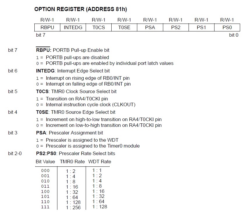
The PSA (bit 3, Prescaler Assignment) should be cleared in order to enable the prescale for TMR0. Setting this would assign the prescale to the watchdog timer (which is discussed in the timers article). You might noticed the INTEDG (bit 6, Interrupt Edge Select) bit which allows you to choose between rising edge or falling edge change in state on the RB0 pin (discussed in the previous section).
Bits 2 to 0 are the prescaler select bits:
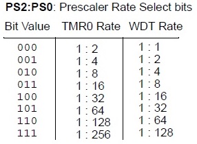
Giving bits 2 to 0 gives you the maximum prescale value of 1:256. This means that TMR0 will now be counting every 256 uS instead of every 1 uS. That's 65280 uS before TMR0 would overflow.
Look at this LED blink code that uses the TMR0 overflow PIC interrupt:
; TODO INSERT CONFIG CODE HERE USING CONFIG BITS GENERATOR
#INCLUDE <PIC16F84A.INC>

RES_VECT  CODE    0x0000            ; processor reset vector
    GOTO    START                   ; go to beginning of program

INT_VECT  CODE	  0x0004	    ; interrupt vector
    GOTO    ISR			    ; go to interrupt service routine


MAIN_PROG CODE                      ; let linker place main program

 START
    BSF STATUS, RP0
    CLRF TRISB ;PORTB all output
    MOVLW b'10100000'
    MOVWF INTCON ;enable timer-overflow interrupt
    MOVLW b'00000111'
    MOVWF OPTION_REG ;instruction clock,falling edge,prescaler set to maximum
    BCF STATUS, RP0 ;switch to Bank 0
    CLRF TMR0 ;initialize timer
    GOTO MAIN

;Interrupt service routine--------------------------------------------------------
ISR
    BCF INTCON, GIE ;Disable all interrupts inside interrupt service routine
    BCF INTCON, T0IF ;disable timer-overflow interrupt flag bit
    BCF PORTB,0 ;clear RB0
    BSF INTCON, GIE ;re-enable all interrupts
    RETFIE

;Main routine---------------------------------------------------------------------
MAIN
    BSF PORTB,0 ;Set RB.0
    GOTO MAIN ;Loop

    END
When the timer is yet to overflow, the code loops inside the main routine which continually sets the RB0 pin. When the timer overflows and the interrupt triggers, the isr routine clears the RB0 pin. This effectively "blinks" a LED if it's connected to RB0. Since maximum value of prescale is set, the blinking speed would be roughly 65 mS.
RB Change Interrupt
You can also attach a PIC interrupt to the pins RB4, RB5, RB6 and RB7 just like how you can with RB0/INT. The RB change interrupt is configured via setting RBIE (bit 3, RB Change Interrupt Enable) of the INTCON register. When any change of state occurs for any of the mentioned pins, the RBIF (bit 0, RB Change Interrupt Flag) of the INTCON register sets. Note that the time it took to change the state must be at least equal to the instruction cycle time.
The example sets RA0 then clears it when a change of state in any of the pins RB.4 to RB.7 occurs.
; TODO INSERT CONFIG CODE HERE USING CONFIG BITS GENERATOR
#INCLUDE <PIC16F84A.INC>

RES_VECT  CODE    0x0000            ; processor reset vector
    GOTO    START                   ; go to beginning of program

INT_VECT  CODE	  0x0004	    ; interrupt vector
    GOTO    ISR			    ; go to interrupt service routine


MAIN_PROG CODE                      ; let linker place main program

 START
    BSF STATUS, RP0
    CLRF TRISA			  ;set all PORTA as OUTPUT
    MOVLW 0xF0
    MOVWF TRISB			  ;buttons attached to RB4 to RB7
    BCF STATUS, RP0		  ;go to bank 0
    MOVLW b'10001000'
    MOVWF INTCON		  ;Global interrupt enabled, RB Change interrupt enabled
    GOTO MAIN

;Interrupt service routine--------------------------------------------------------
ISR
    BCF INTCON, GIE ;Disable all interrupts inside interrupt service routine
    BCF PORTA,0 ;clear RA.0
    BCF INTCON,RBIE ;Clear external interrupt flag bit
    BSF INTCON, GIE ;Enable all interrupts on exit
    RETFIE

;Main routine---------------------------------------------------------------------
MAIN
    BSF PORTA,0 ;Set RA.0
    GOTO MAIN ;Loop

    END
EEPROM Write Interrupt
Writing to the EEPROM location of the PIC takes around 10 ms, a long wait for microcontrollers. This is practically why this PIC interrupt source exist: so that the PIC can do other useful things while writing data to the EEPROM. Setting EEIE (bit-6) enables this interrupt and EEIF (bit-4) is the corresponding flag bit.
The example code below clears RA0, writes data to the EEPROM then sets RA0 when the EEPROM write is complete.
; TODO INSERT CONFIG CODE HERE USING CONFIG BITS GENERATOR
#INCLUDE <PIC16F84A.INC>

RES_VECT  CODE    0x0000            ; processor reset vector
    GOTO    START                   ; go to beginning of program

INT_VECT  CODE	  0x0004	    ; interrupt vector
    GOTO    ISR			    ; go to interrupt service routine


MAIN_PROG CODE                      ; let linker place main program

 START
    BSF STATUS, RP0		  ;go to bank 1
    CLRF TRISA			  ;set all PORTA as OUTPUT
    BSF EECON1, WREN ; Enable Write
    ; this is a required sequence according to the datasheet
    MOVLW 55h
    MOVWF EECON2 ; Write 55h
    MOVLW 0AAh ;
    MOVWF EECON2 ; Write AAh
    BSF EECON1,WR ; Set WR bit
    ; end of required sequence
    BCF STATUS, RP0		  ;go to bank 0
    BCF PORTA,0 ;clear RA0
    MOVLW 0FFh ;write 0FFh to EEDATA
    MOVWF EEDATA
    MOVLW b'11000000'
    MOVWF INTCON		  ;Global interrupt enabled, EEPROM write interrupt enabled
    GOTO START

;Interrupt service routine--------------------------------------------------------
ISR
    BCF INTCON, GIE ;Disable all interrupts inside interrupt service routine
    BCF INTCON,EEIE ;Disable EEPROM write interrupt bit
    BSF PORTA,0 ;clear RA.0
    BSF INTCON,EEIE ;Enable EEPROM write interrupt bit
    BSF INTCON, GIE ;Enable all interrupts on exit
    GOTO START


    END
Interrupts in XC8
In XC8, interrupts are given their own interrupt data type. This means you can create ISRs as functions with interrupt as the return type. For example, this is how you would implement the same external interrupt code above in XC8:
#define _XTAL_FREQ 4000000
#include <xc.h>

void main(void) {
    TRISB0 = 1;         //Initialize RB0 as input
    GIE = 1;            //Enable Global Interrupt
    INTE = 1;           //Enable External Interrupt

    while(1){
        RA0=1;          //Set RA0
    }
}
//Interrupt Handler. Note you can use other function name as long as interrupt data type is there
void interrupt isr(void){
    if(INTF){    //Check if External Interrupt Flag is set
        RA0=0;         //Clear RA0 on interrupt
        __delay_ms(100);
        INTF=0;       //External Interrupt Flag must be cleared manually
    }
}
As you see, there is a need to check the external interrupt flag INTF to check if that is indeed the interrupt that triggered because any interrupt can trigger the isr() function.
The timer interrupt would be coded like this:
#define _XTAL_FREQ 4000000
#include <xc.h>

void main(void) {
    TRISB = 0;      // Initialize PORTB as all output
    GIE = 1;        // Enable Global Interrupt
    T0IE = 1;       // Enable Timer Interrupt
    T0CS = 0;   // Timer Clock Source is internal clock
    PS = 7;     // Maximum Prescale

    while(1){
        RB0=1;       //Set RB0
    }
}
//Interrupt Handler. Note you can use other function name as long as interrupt data type is there
void interrupt isr(void){
    if(T0IF){  // Check if Timer Interrupt Flag is set
        RB0 = 0;       // Clear RB0 on interrupt
        T0IF = 0; // Timer Interrupt Flag must be cleared manually
    }
}
How would you code RB change and EEPROM write complete interrupts in XC8?

