
There are instances when digital systems need to interface with devices that produce analog signals, such as sensors and radio equipment. In such cases, the digital system, such as a microcontroller, needs an analog-to-digital converter (ADC) to handle the analog signal.
The ADC Registers
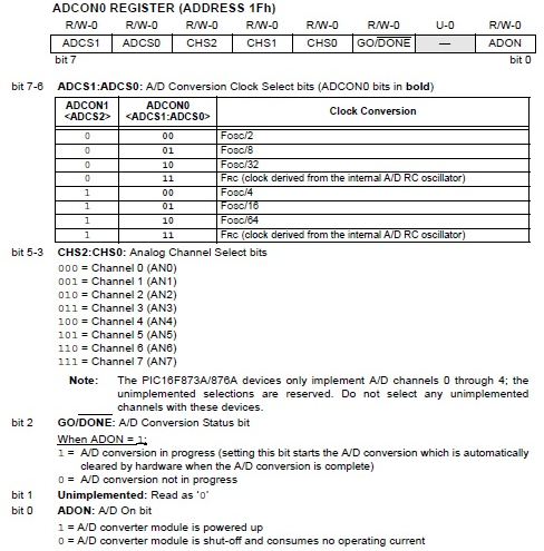
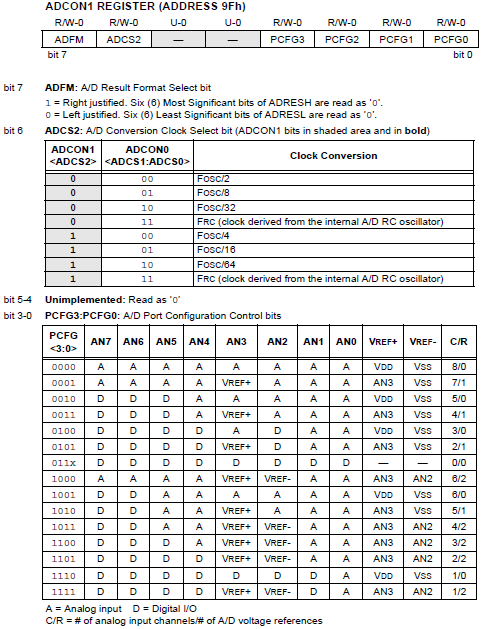
The PIC microcontroller has the registers ADCON0 and ADCON1 that control the conversion. The PIC16F877A has a 10-bit ADC whose results are stored in two registers: ADRESH and ADRESL. The ADCON0 and ADCON1 registers with their corresponding bits are shown:
Sampling Time
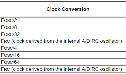
An analog, or time-varying, signal is continually sampled at equal time intervals at a frequency that maxes out at twice the highest frequency of that signal (known as the Nyquist Theorem). Naturally, the sampling frequency of the microcontroller is determined by its oscillator value. The PIC16F877A datasheet does not mention the sampling frequency but gives the conversion time (TAD) which is chosen among these values:
The conversion time for the internal RC source is typically 4 us but can vary from 2 to 6 us.
According to the datasheet, each conversion takes up to a minimum of 12 TAD. Also, the oscillator value must be chosen to produce at least a TAD of 1.6 us. For example, it would take 96 us for the conversion to complete for Fosc/32 if a 4 MHz crystal is used:
12 TAD = 12 * 2 * 1/4000000 = 0.000096 seconds
Using a 4 MHz crystal is unadvisable for the Fosc/2 setting because it would not reach the minimum 1.6 us:
TAD = 2 * 1/4000000 = 0.0000005 seconds
Bit Justification
Since the 10-bit result is stored in two registers, there is an option to right-justify or left-justify the results. For example, a 5V analog signal which is “represented” by a value 1023 ((5/(210 – 1)) * 5 = 1023) would be 11111111112 in binary.
This result is divided into two but would vary if left or right justified. If right-justified, the lower 8 bits is stored in ADRESL while the highest two bits will be the LSBs of ADRESH. If left-justified, the highest 8 bits will be stored in ADRESH while the remaining two bits will be the two MSBs of ADRESL.
This would result in two different values depending on how you would combine ADRESH and ADRESL into a single 16-bit variable:
Right justified: 5 V -> 00000011111111112 ->1023
Left justified: 5 V -> 11111111110000002 -> 65472
Conversion Time
The conversion process begins once the GO_DONE bit is set (ADCON0, 2). This is also the flag bit that is automatically cleared when the conversion is done. The next conversion can commence at the specified accuracy if the required acquisition time has passed. The acquisition time is calculated using the formula:
Amplifier Settling Time + Hold Capacitor Charging Time + Temperature Coefficient
The hold capacitor charging time is calculated using:
CHOLD (RIC + RSS + RS) In(1/2047)
A sample computation is given by the PIC16F877A datasheet:
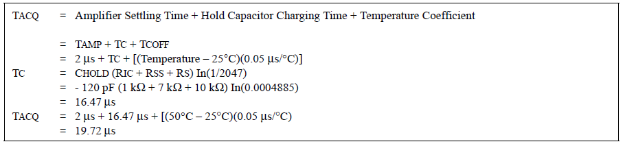
This means at least 19.72 us must pass between conversions. The recommended analog source impedance (Rs in the formula) is 2.5 kΩ. Impedance lesser than this will cause the acquisition time to also decrease. Confusingly, the example computation from the datasheet (as shown above) shows Rs to be 10 kΩ.
An interrupt can also be configured to trigger when the conversion is complete. This is done by setting the ADIE bit (bit 6) of the PIE1 register.
Steps in Configuring PIC ADC
In summary, here are the steps to be followed when setting up the PIC16F877A ADC:
1. Configure the A/D module:
- Configure analog pins/voltage reference and digital I/O (ADCON1)
- Select A/D input channel (ADCON0)
- Select A/D conversion clock (ADCON0)
- Turn on A/D module (ADCON0)
2. Configure A/D interrupt (if desired):
- Clear ADIF bit
- Set ADIE, PEIE and GIE bits
3. Wait for the required acquisition time.
4. Start conversion:
- Set GO/DONE bit (ADCON0)
5. Wait for A/D conversion to complete by either:
- Polling for the GO/DONE bit to be cleared (interrupts disabled); OR
- Waiting for the A/D interrupt
6. Read the A/D Result register pair (ADRESH:ADRESL), clear bit ADIF if required.
7. For the next conversion, go to step 1 or step 2 as required. The A/D conversion time per bit is defined as TAD
C Function for PIC ADC
Here’s a function in XC8 that uses the PIC16F877A ADC:
unsigned int ADC_read(int channel){
    ADFM = 1; //results right justified
    ADCS0 = 0; //conversion speed = 4*Tosc
    ADCS1 = 0;
    ADCS2 = 1;
    ADCON0bits.CHS = channel;
    ADON = 1; //turn on ADC
    __delay_ms(1);   //should be enough to cover acquisition time
    GO_DONE = 1;
    while(ADCON0bits.GO_DONE == 1);
    unsigned int adval = (ADRESH << 8) + ADRESL;
    return adval;
}
To use the function, just call ADC_read(channel) where the channel can be from 0 to 7. It is advisable to introduce a delay between reads that covers the conversion period. Note that clearing the GO_DONE bit before the end of the conversion period will stop the conversion and will discard the incomplete conversion result.
The returned 16-bit integer value (adval) on the function above can be printed out to the serial port or to an LCD by first converting it to string. XC8 has the itoa() function for that. Here’s a code that prints out the ADC result on the serial port:
#include <xc.h> // include processor files - each processor file is guarded.
#include <stdio.h>
#include <conio.h>
#include <stdlib.h>
void Serial_init(const long int baudrate){
    BRGH = 1;
    unsigned int x;
    x = (_XTAL_FREQ /(baudrate*16))-1;
    SPBRG = x;
    SYNC = 0;
    SPEN = 1;
    TRISC7 = 1;
    TRISC6 = 1;
    CREN = 1;
    TXEN = 1;
}
void putch(char data) {
    while(!TRMT);
    TXREG = data;
}
unsigned int ADC_read(int channel){
    ADFM = 1; //results right justified
    ADCS0 = 0; //conversion speed = 4*Tosc
    ADCS1 = 0;
    ADCS2 = 1;
    ADCON0bits.CHS = channel;
    ADON = 1; //turn on ADC
    __delay_ms(1);
    GO_DONE = 1;
    while(ADCON0bits.GO_DONE == 1);
    unsigned int adval = (ADRESH << 8) + ADRESL; //ex 1002
    return adval;
}
void main(void) {
    Serial_init(9600);
    int adval = ADC_read(0); //read analog signal at channel 0
    char buf[5];             //buffer to hold conversion result from integer to string
    itoa(buf, adval, 10);    //convert integer ADC result to string and store to buf
    printf("\rValue: %s\n",buf);  //print through Serial port
    __delay_ms(10);
}
With knowledge on PIC ADC, you can now interface your microcontroller with a variety of sensors that give out voltages in relation to the parameter they are sensing. A popular temperature sensor is the LM35, which gives 10 mV per degree Celsius.

