
To continue with our tutorial on synchronous serial with PICs, we will know look at I2C, another popular protocol used by sensors, displays and memory devices.
I2C vs. SPI
I2C answers some of the problems of SPI including no multi-master mode, no slave flow control and more pins to use. But in terms of speed, SPI is still faster due to its push-pull driver compared to the open-collector driver for I2C. In fact the fastest I2C mode, Ultra Fast, can reach only up to 5 MHz while some SPI busses can reach 50 MHz.
Read the I2C Protocol Guide for more information on I2C.
The PIC16F877A MSSP, which is responsible for both I2C and SPI, allows only up to 400 kHz on the I2C bus which is the Fast-mode rate. This rate is only achievable if an oscillator of at least 10 MHz is used. [From Section 30 p 29 of Mid-range Family Technical Manual]. The 100 kHz standard mode is also supported needing at least 1.5 MHz of clock speed.
[the_ad id="3059"]
The MSSP in I2C Mode
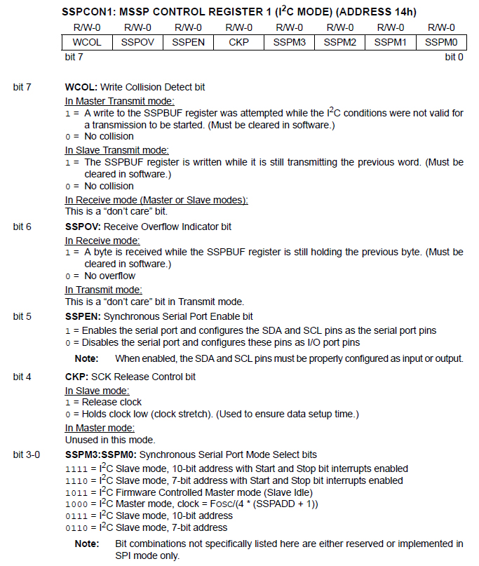
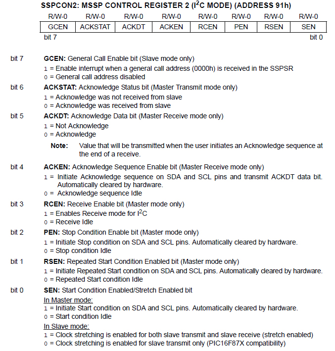
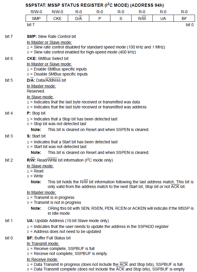
In I2C mode, the MSSP module use the SSPCON, SSPCON2 and SSPSTAT registers to configure both master and slave devices. Here they are again:
Configuring MSSP to I2C Mode
Here’s a typical sequence in configuring I2C:
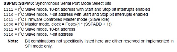
- Enable the SDA and SCL pins by setting SSPEN in SSPCON and select master or slave mode through bits SSPM3:SSPM0:
- If in master, configure the ACKSTAT, ACKDT, ACKEN, RCEN, PEN, RSEN and SEN bits on SSPCON2. Normally, these bits are just cleared.
- If in slave, set CKP in SSPCON and configure the GCEN bit in SSPCON2 which is also normally cleared.
- If in master or slave, configure SMP, CKE, and UA (if 10-bit addressing) in SSPSTAT. Note that the master and slave must have the same settings for these three.
- If in master, calculate the correct SSPADD for the transmission speed using the formula:
![]()
For example, if 100 kHz speed is desired using a 4 MHz oscillator then
![]()
- There is also a need to set RC3 (SCL) and RC4 (SDA) as input.
- An interrupt in the slave device is needed to signal if data is received from the I2C bus. This is done by setting SSPIE and PEIE on the INTCON and PIE1 registers accordingly.
[the_ad id="3059"]
Sending I2c Data
The normal sequence in sending data in an I2C bus is like this:
START -> SLAVE ADDRESS -> REGISTER ADDRESS (if applicable) -> DATA (to be written or read) -> STOP
To send data as master, a start condition is signalled by setting SEN bit. Then the address of the slave device is sent, followed by the register address (most I2C sensors have this) where the data is to be sent or read followed by the data to be sent or read on that device.
The stop condition is then signaled by setting PEN bit. Note that the MSSP can be overwhelmed if the mentioned sequence are done in succession. Checking if R/W bit is set or any of the bits ACKEN, RCEN, PEN, RSEN and SEN has been set is a good way to avoid overwhelming.
To receive data as slave, the SSPIF bit is checked upon interrupt. If this bit is set then data has been received from the I2C bus. The data is then read from SSPBUF provided that the data was received not address (checked using the D/A bit of SSPSTAT) and that the bus is in read mode (set using the R/W bit of SSPSTAT).
Example Implementation using XC8
PIC to PIC communication using I2C would look like this:
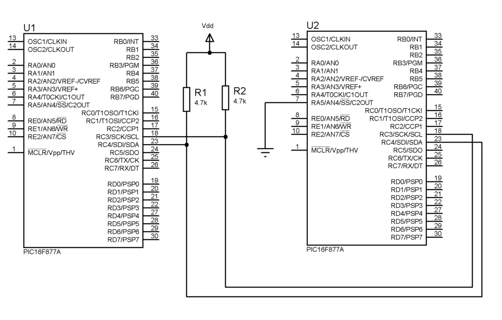
Note the 4.7 kΩ pull-up resistor which is typical in I2C.
[the_ad id="3059"]
Here’s how to implement I2C on PIC16F877A using XC8:
Master Mode:
#define _XTAL_FREQ 4000000
#include <xc.h>

void i2cWait(){
   while(R_nW || (SSPCON2 & 0x1F));
   return;
}
void main(void) {
   SSPCON = 0x28;         //I2C Master mode, SDA and SCL pins enabled
   SSPCON2 = 0;           //Default settings
   SSPADD = 99;           //Calculated using Fosc/(4*speed) - 1 where speed is 10000
   SSPSTAT = 0;           //Default settings
   TRISC = 0x18;          //RC3 (SCL) and RC4 (SDA) as inputs

   int i = 0;

   while(1){
       i2cWait();
       SEN = 1;           //start condition
       i2cWait();
       SSPBUF = 0x30;     //7-bit address of slave device plus 0 for write
       i2cWait();
       SSPBUF = i;        //data to be sent
       i2cWait();
       PEN = 1;           //stop condition
       __delay_ms(100);

       i++;               //increment data value
   }
}
Slave Mode:
#define _XTAL_FREQ 4000000
#include <xc.h>

short d;

void main(void) {
   SSPCON = 0x36;         //I2C 7-bit Slave mode, clock released, SDA and SCL pins enabled
   SSPCON2 = 0x01;        //Enable clock stretching for both slave transmit and slave receive
   SSPADD = 0x30;         //Slave address
   SSPSTAT = 0x80;        //Slew rate control disabled since 10000 is used
   TRISC = 0x18;          //RC3 (SCL) and RC4 (SDA) as inputs
   GIE = 1;               //Enable all unmasked interrupts
   PEIE = 1;              //Enable all peripheral interrupts
   SSPIF = 0;             //Clear SSP interrupt flag
   SSPIE = 1;             //Enable SSP interrupt
   TRISB = 0;

   while(1){}

}

void interrupt i2c_slave_read(){
   if(SSPIF){
       CKP = 0;            //pull clock low
       if(!D_nA && !R_nW){ // not address and in write mode
           d = SSPBUF;     //there is a need to read SSPBUF first
           while(!BF);     //wait for buffer to empty
           PORTB = SSPBUF;  //show contents of SSPBUF
           CKP = 1;        //pull clock high
       }
       SSPIF = 0;          //clear interrupt flag upon exit
   }
}
Here, the i variable is incremented and sent to the slave via the I2C bus. When the data is received by the slave, it is moved to the PORTB register.
Once you’re familiar with how the I2C protocol works with PICs, you can now use I2C devices like MPU6050 accelerometer or the BMP280 barometric pressure and altitude sensor.
[the_ad id="3059"]

