
Pulse width modulation may have been invented to encode messages into pulsing signal but it was originally conceived as a technique for controlling power supplied to motors. In this tutorial, we will look at how PIC16 PWM works.
The CCP Module
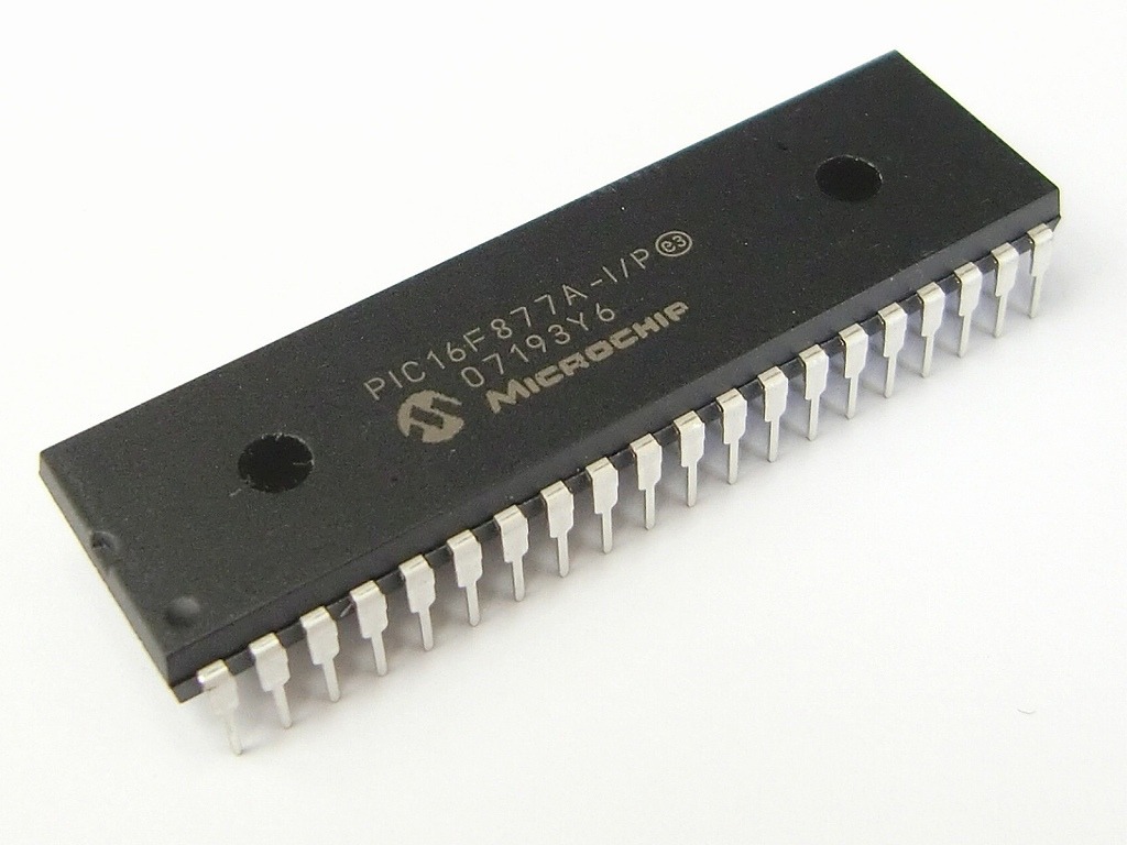
PWM with PIC16F877A is achieved using the Capture/Compare/PWM (CCP) module. This microcontroller has two CCP pins: CCP1 at #17 (RC2) and CCP2 at #16 (RC1). Each pin has a corresponding CCP register, CCP1CON and CCP2CON:
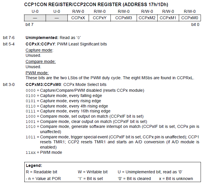
Capture and compare will be covered in another tutorial. You’ll see that we only have a few bits for concern: CCPxX:CCPxY and CCPxM3:CCPxM0.
[the_ad id="3059"]
Duty Cycle and Period
According to the image above, the former is the two least significant bits of the PWM duty cycle. Duty cycle is the high portion of the pulse and is calculated using the formula:
The PWM period is the length of one pulse and is calculated using the formula:
Naturally, the period is longer than the duty cycle as shown in the figure below:
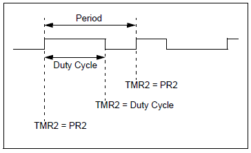
However, you may (accidentally) set the duty cycle greater than the period. If this happens then the CCP pin will not produce a PWM signal.
[the_ad id="3059"]
For example, the following code in XC8 will produce a duty cycle of 400 us with a period of 819 us:
#define _XTAL_FREQ 20000000
#include <xc.h>

void main(void) {
  PR2 = 255;
  CCPR1L = 0b01111101;
  CCP1CONbits.CCP1X = 0;
  CCP1CONbits.CCP1Y = 0;
  TRISC2 = 0;
  T2CON = 3;
  T2CONbits.TMR2ON = 1;
  CCP1CONbits.CCP1M3 = 1;
  CCP1CONbits.CCP1M2 = 1;
  __delay_ms(10);
  while(1){;}
}
Here’s the calculations using the settings in the code:
C Code for PWM
Now we want to create a code wherein we can just specify the PWM frequency and duty cycle. Here’s what I did: I created a function that will calculate PR2 based on the given frequency:
void initPWM(double freq, int duty, int channel){
   PR2 = _XTAL_FREQ / (4*freq*TMR2Pre) - 1;
Where TMR2Pre is equal to the TMR2 Prescale value.
I also added within the same function a routine that will compute the values of CCPRXL:CCPXCON<5:4> based on a given duty cycle.
int ccpr1l_ccp1con, ccpr2l_ccp2con;
int dc_max = _XTAL_FREQ/(1023*TMR2Pre);
int dc = 100*freq/duty;

if(channel == 1){
  ccpr1l_ccp1con = _XTAL_FREQ / dc * TMR2Pre;
  CCPR1L = (ccpr1l_ccp1con & 0b0000111111111100) >> 2;
  CCP1X = ccpr1l_ccp1con & 2;
  CCP1Y = ccpr1l_ccp1con & 1;
}
if (channel == 2){
  ccpr2l_ccp2con = _XTAL_FREQ / dc * TMR2Pre;
  CCPR1L = (ccpr1l_ccp1con & 0b0000111111111100) >> 2;
  CCP1X = ccpr1l_ccp1con & 2;
  CCP1Y = ccpr1l_ccp1con & 1;
}
The input duty cycle must be a percentage from 1 to 100.
Another function was created to turn on PWM:
void startPWM(int channel){
  if(channel == 1){
    TRISC2 = 0;
    CCP1M3 = 1;
    CCP1M2 = 1;
  }
  if(channel == 2){
    TRISC1 = 0;
    CCP2M3 = 1;
    CCP2M2 = 1;
  }
  T2CON = 3;
  TMR2ON = 1;
}
These functions are saved into a header file named “pwm.h”. Now, because of how the PWM period and duty cycle are computed, there are minimum and maximum frequencies depending on the choice of oscillator and TMR2 prescale. I calculated the values for two oscillator values:
- Prescale 16 at 20 MHz: 1.22k to 312.5 kHz
- Prescale 4 at 20 MHz: 4.882k to 1.25 MHz
- Prescale 1 at 20 MHz: 19.53k to 5 MHz
- Prescale 16 at 4 MHz: 243.19 to 62.5 kHz
- Prescale 4 at 4 MHz: 4.863k to 1.25 MHz
- Prescale 1 at 4 MHz: 1.215k to 312.5 kHz
Here’s a full example code that utilizes "pwm.h" to generate around 50% duty cycle at 500 Hz:
#define _XTAL_FREQ 4000000
#define TMR2Pre 16
#include <xc.h>
#include "pwm.h"

void main(void) {
  initPWM(500, 50, 1);
  startPWM(1);
  return;
}

