
A Passive Infrared (PIR) sensor is a popular sensor for detecting the presence of a person. This is a type of proximity sensor although you may also call it a motion sensor. This tutorial aims to guide you in using a PIR sensor with your NodeMCU ESP8266 WiFi board.
Introduction
The human body emits infrared signals by virtue of its temperature. When a person is near a PIR sensor, the infrared detector triggers and the voltage on the output pin goes low.
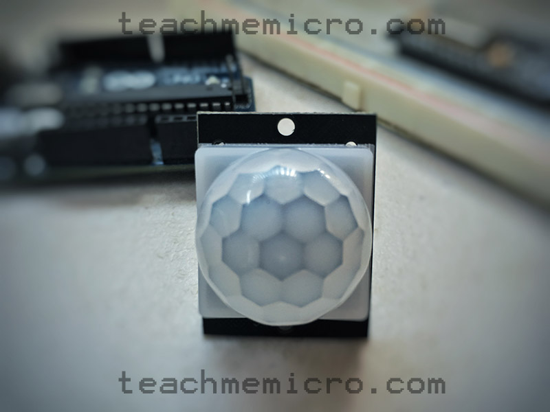
To enhance the reception of infrared signals, PIR sensors often come with a Fresnel dome. Most of the time, the dome is removable as shown below:
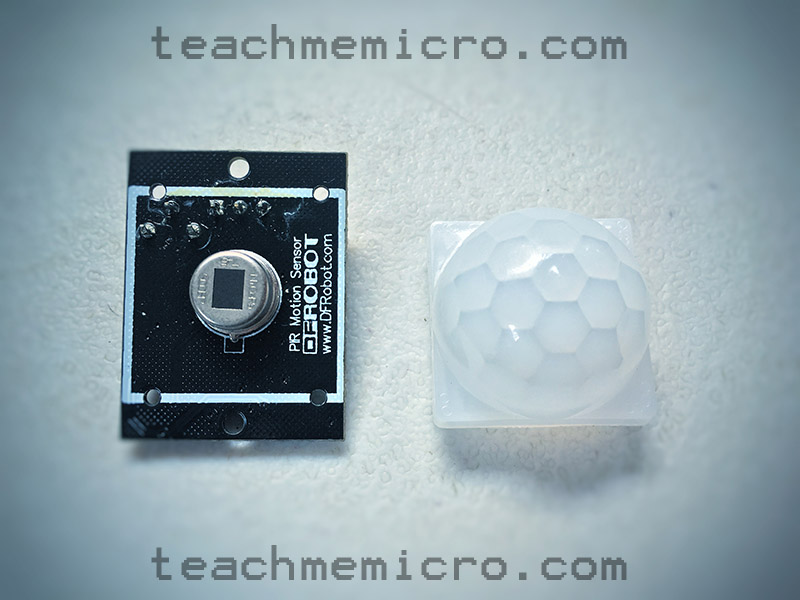
Removing the dome reveals the infrared receiver. The sensor will still work but will only detect persons directly in front of the receiver.
How to Connect to a PIR Sensor
PIR sensor modules commonly have three output pins: VCC, OUT and GND.
For DFRobot's PIR Sensor Board:

1 - OUT
2 - VCC
3 - GND
4 - Trigger Select
5 - Sensitivity Adjust
For HC-SR501 Board:

The VCC pin connects to the positive source voltage of any microcontroller board. PIR sensor modules will work with both 3.3V and 5V levels. Thus, it is safe to connect the VCC pin of the PIR sensor to any of the 3.3V of the NodeMCU. The GND pin, of course, connects to the GND pin of the NodeMCU.
The OUT pin connects to any digital pin of the NodeMCU. This pin will go low when the sensor triggers.
Remember that the numbers on the board is different from the numbers used in programming. The NodeMCU pinout guide will help you with the correct pin numbers.
Most modules contain a knob for adjusting sensitivity and a jumper for trigger selection. These are covered in a separate PIR sensor article.
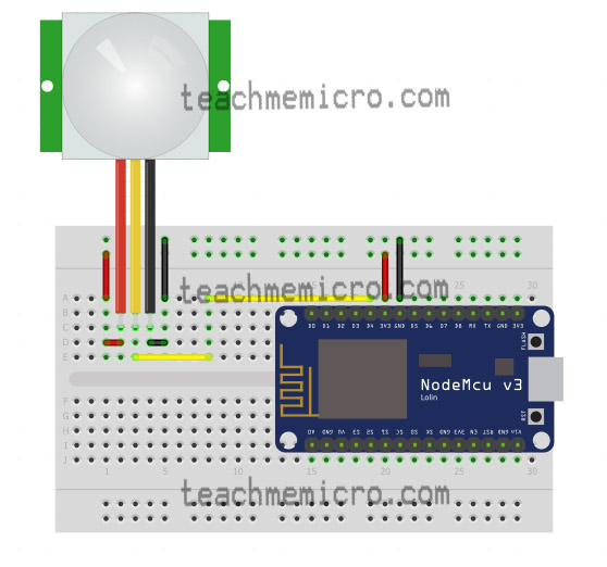
For the rest of this tutorial, we will follow this wiring diagram:
Programming the NodeMCU with PIR Sensor
Before continuing, make sure to read how to use an Arduino IDE to program the NodeMCU.
We’ll start with a basic sketch that will give an output on the serial monitor every time the PIR sensor triggers.
 const int PIRSensorOutPin = 2;    //PIR Sensor OUT Pin
 void setup() {
    Serial.begin(9600);
    pinMode(PIRSensorOutPin, INPUT);
 }
 void loop()
 {
    if (digitalRead(PIRSensorOutPin) == LOW)
    {
       Serial.println("Person detected!");    //Print to serial monitor
    }
    else {;}
 }
As you can see, the sketch is straightforward. We use the same function we used to read a button:
digitalRead(PIRSensorOutPin)
We then insert the function above in an if-else statement and execute a print to serial if the if-else returns a zero.
 if (digitalRead(PIRSensorOutPin) == LOW)
 {
    Serial.println("Person detected!"); //Print to serial monitor
 }else{;}
The full sketch above is useful for testing if your PIR sensor is working.
However, since we are using a NodeMCU instead of an Arduino in this tutorial, it is best to use the board as it is meant to.
Instead of giving an output to the serial monitor every time a person is detected, we will give an output to a web page hosted by the NodeMCU.
For this example project, we will modify the example sketch that comes with this tutorial. AJAX is helpful here so that the page will update automatically when the PIR sensor triggers.
This is now the modified sketch:
#include <ESP8266WiFi.h>
#include <WiFiClient.h>
#include <ESP8266WebServer.h>

// Replace with your network credentials
const char* ssid = "<Your-WiFi-SSID>";
const char* password = "<Your-WiFi-Password>";
ESP8266WebServer server(80);   //instantiate server at port 80 (http port)

String page = "";
String text = "";

int PIRSensorOutputPin = 2;
bool isTriggered = false;

void setup(void){
 pinMode(PIRSensorOutputPin, INPUT);
 delay(1000);
 Serial.begin(115200);
 WiFi.begin(ssid, password); //begin WiFi connection
 Serial.println("");

 // Wait for connection
 while (WiFi.status() != WL_CONNECTED) {
 delay(500);
 Serial.print(".");
}

 Serial.println("");
 Serial.print("Connected to ");
 Serial.println(ssid);
 Serial.print("IP address: ");
 Serial.println(WiFi.localIP());
 server.on("/data.txt", [](){
   if(isTriggered){
     text = "Person Detected!";
   }else{
     text = "";
   }
   server.send(200, "text/html", text);
 });
 server.on("/", [](){
   page = "<h1>PIR Sensor to NodeMCU/h1><h1>Data:</h1> <h1 id=\"data\">""</h1>\r\n";
   page += "<script>\r\n";
   page += "var x = setInterval(function() {loadData(\"data.txt\",updateData)}, 1000);\r\n";
   page += "function loadData(url, callback){\r\n";
   page += "var xhttp = new XMLHttpRequest();\r\n";
   page += "xhttp.onreadystatechange = function(){\r\n";
   page += " if(this.readyState == 4 && this.status == 200){\r\n";
   page += " callback.apply(xhttp);\r\n";
   page += " }\r\n";
   page += "};\r\n";
   page += "xhttp.open(\"GET\", url, true);\r\n";
   page += "xhttp.send();\r\n";
   page += "}\r\n";
   page += "function updateData(){\r\n";
   page += " document.getElementById(\"data\").innerHTML = this.responseText;\r\n";
   page += "}\r\n";
   page += "</script>\r\n";
   server.send(200, "text/html", page);
});

 server.begin();
 Serial.println("Web server started!");
}

void loop(void){
 if(digitalRead(PIRSensorOutputPin) == 0){
     isTriggered = true;
 }else{
     isTriggered = false;
 }
 server.handleClient();
}
Upload this sketch to the NodeMCU, providing your own WiFi SSID and password on lines 6 and 7. When successful, the serial monitor will give you an IP address. Use a browser and visit that IP address. The page should display "Person detected!" when the sensor is triggered.
Was the tutorial helpful? Kindly comment below for any questions or suggestions you have for this tutorial.

