
Lack of pins to use is a common challenge in designing microcontroller-based projects. This is particularly true when dealing with liquid crystal or seven-segment displays. Multiplexers and display drivers are great help but at an additional cost. Thankfully, a software-based solution exists to solve such a problem.
What is POV?
Persistence of vision (POV) is a technique to reduce the microcontroller pins used without adding extra components. Basically, it’s a form of optical illusion wherein our perception of an object is not as fast as how the object is changing. A basic non-electronic example of POV is how a pencil seemed rubbery when wiggled.
POV With Seven-Segment Displays
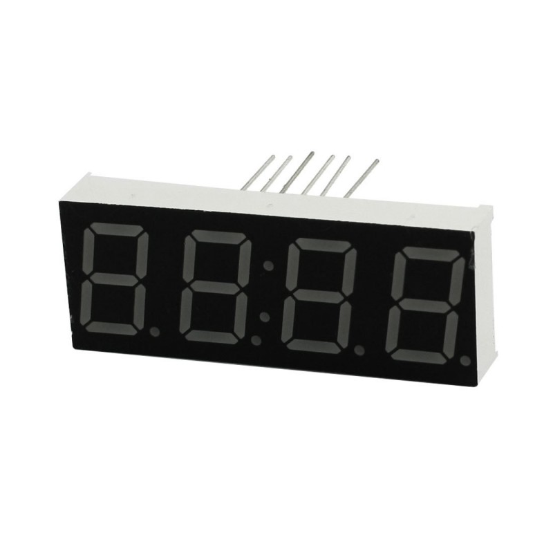
I will be using common cathode (CC) seven-segment displays for this tutorial. I believe this is enough to grasp the basics of POV and lay the path for using other devices like sixteen-segment displays, dot matrices, etc.
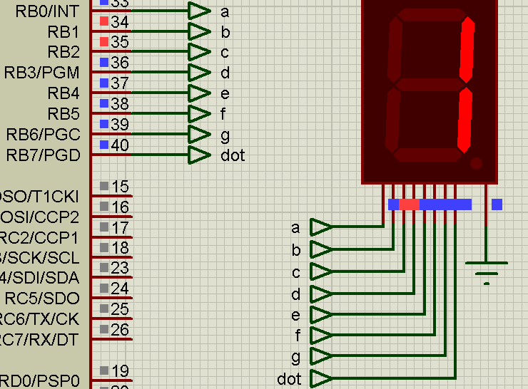
Recall that a seven-segment display is wired like this:

To light up one segment, the anode of that segment must have a higher voltage than the cathode. Each segment can be assigned to a microcontroller pin and the cathode is connected to the ground.
Numbers are displayed by setting (make high) certain segments. If the wiring connection below is followed, then digit one is displayed when RB.1 and RB.2 of the PIC16F84A are set while the rest are cleared (make low).
Displaying digits 0 to 9 is done by following the table below:
| Bit Sequence | 7-segment Digit |
|---|---|
| 00111111 | 0 |
| 00000110 | 1 |
| 01011011 | 2 |
| 01001111 | 3 |
| 01100110 | 4 |
| 01101101 | 5 |
| 01111110 | 6 |
| 00000111 | 7 |
| 01111111 | 8 |
| 01100111 | 9 |
But what if we use more than one seven-segment display? This is where POV comes in handy. The concept is tricking the eye as if two displays are simultaneous although they are actually just alternating.
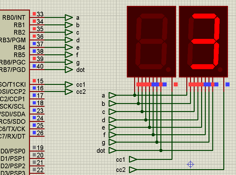
Consider this connection:
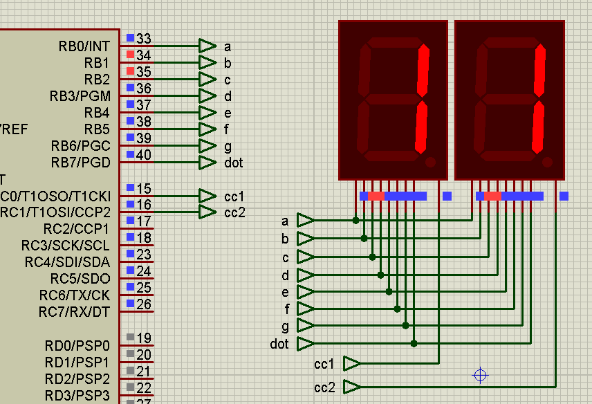
Here we see that the cathodes for the displays are now connected to a pin. The segments for both displays are connected to the same pins! We can turn on the left display if its cathode is low and turn it off if its cathode is high. The same is true for the right display.
Now if we want to display the digit 13 on these two displays, what we do is turn on the left display and turn off the right display. Then, we make the segments display the digit one:
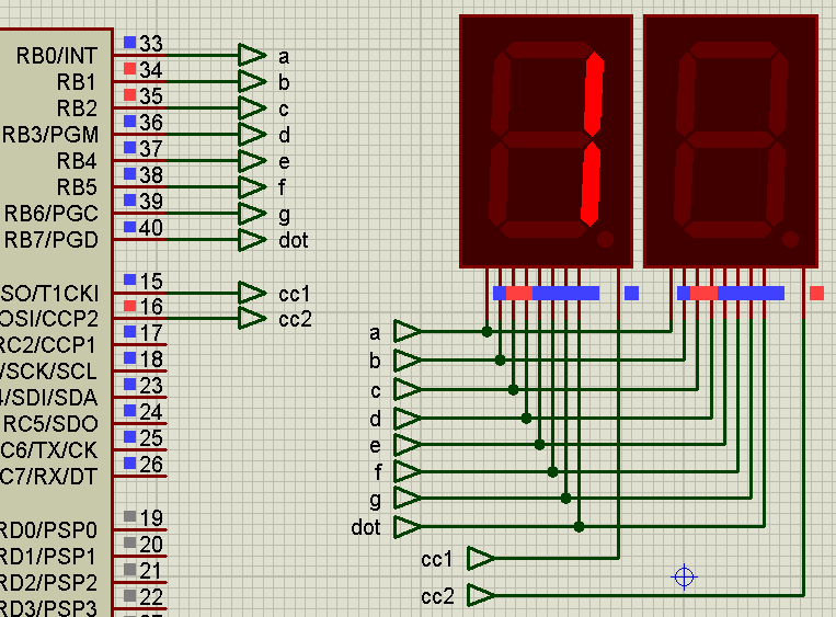
After this, we turn off the left digit and turn on the right digit. Then, we make the segments display the digit three:
Now, we make this loop in a speed that is fast enough to trick the eye that they are simultaneous:
That’s POV!
Example Project with POV
We can extend this to as many seven-segment displays as our chosen microcontroller can permit. The limiting factor is the number of available pins for the cathode of each display.
In the video above, I used POV to create a digital clock out of six seven-segment displays and one PIC microcontroller. To further reduce the pin count, I used a BCD to seven-segment driver.

